|
Quite early in the process
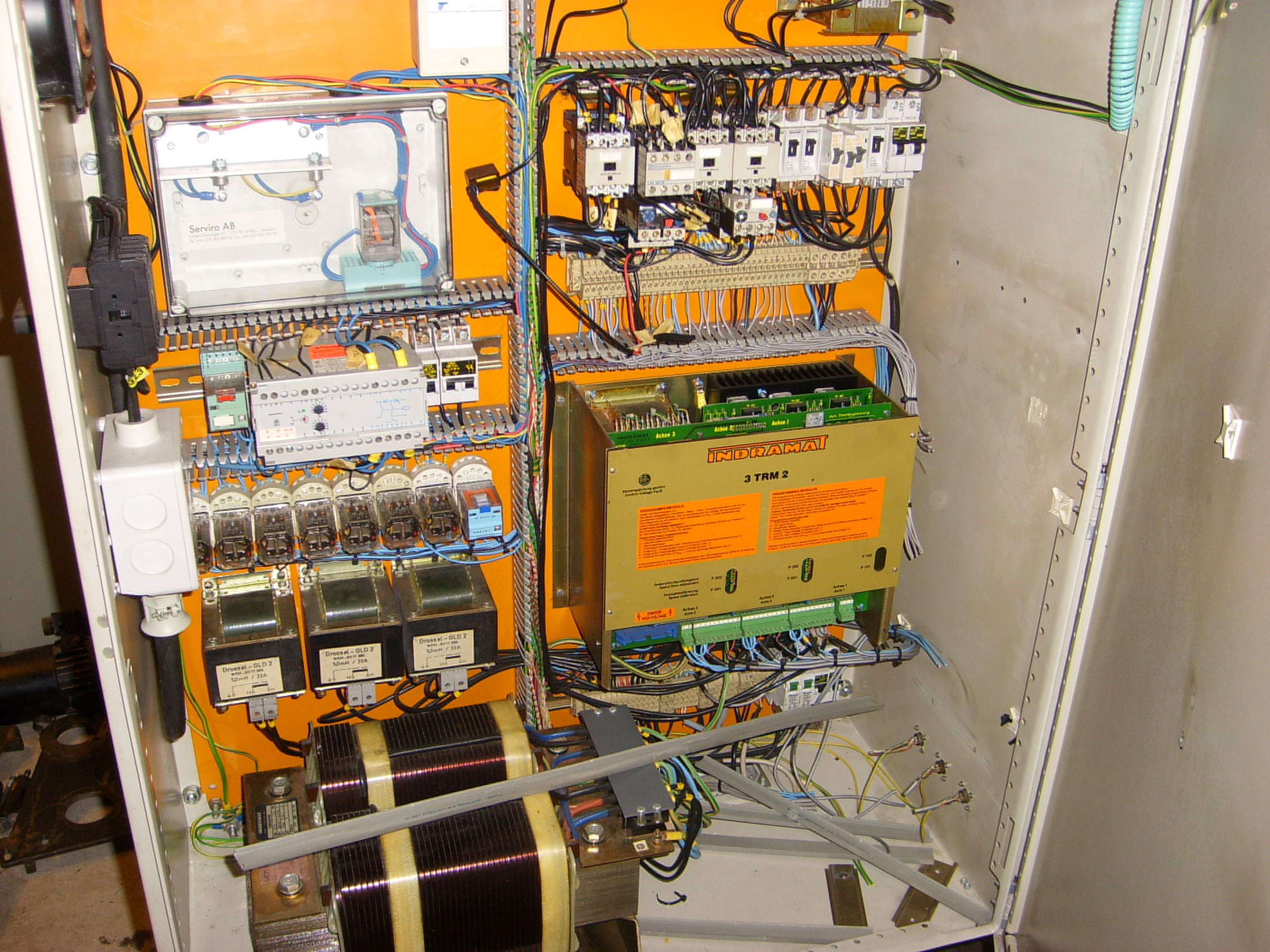
I stripped out everything in the original
electrical cabinet and
removed the mounting panel to make it easier to mount
all the new stuff. Circuit brakers, contactors, relays,
resistors, servodrives, spindle drive, break-out-board
etc etc.
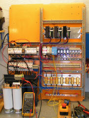
Pretty basic stuff here
so far. Fuses for the various powersupplies, VFD, and
computer. Contactors and power resistors for the
softstart circuit of the main transformer and inrush
limiter for the main filer capacitors. Two of the three
remaining resisotrs are for the powerdump circuit and
the third is a bleeder that quickly discharges the
powersupply capacitors.
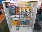
A 24VDC powersupply for
the control voltage, a proper E-stop relay (the blue box
in the middle) and a row of terminals for
interconnections.
The main powersupply
transformer3-phase rectifier and filter capacitors with
the powerdump circuit on top. Basically I'm just testing
the softstart and E-stop circuits.
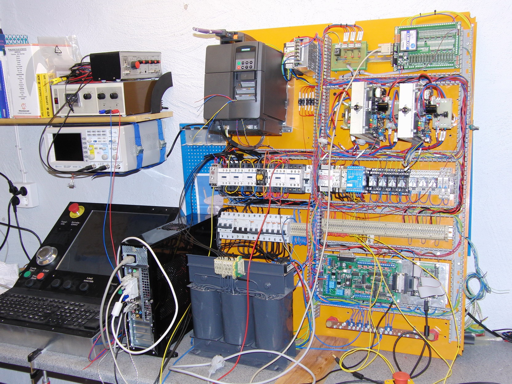
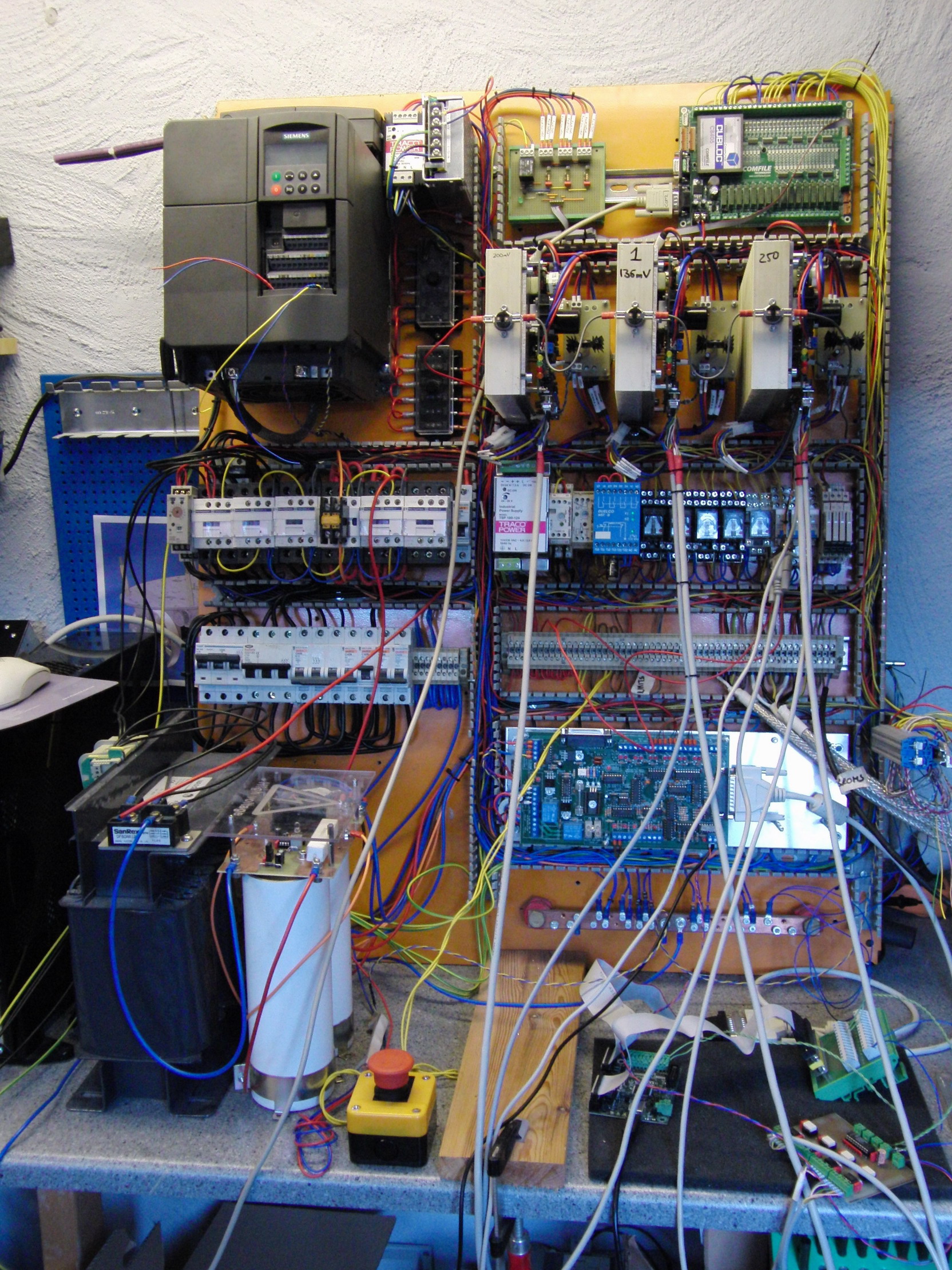
Here you
can see that I've removed the VSD-A drives and installed
(2 out of three) HP-UHU drives instead, the VFD for
the spindledrive have been mounted, break-out-board,
CUBLOC PLC for the control-panel and various other
things. You can also get a glimse of the control panel I
designed for this project.

The HP-UHU servo drive
have a combined fault input/output. If the fault I/O on
all the drives are connected together they will all
stop if any one faults. This is nice and all but the
problem is you have no way of knowing which one that
caused the fault in the first place. So I designed a
circuit that with the help of the CUBLOC PLC and some
ladder logic latches the fault state of the offending
drive and then stops the others. The CUBLOC is connected
to Mach3 via MODBUS so I can make Mach3 show me which
drive it was that caused the fault.
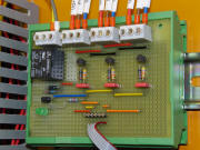
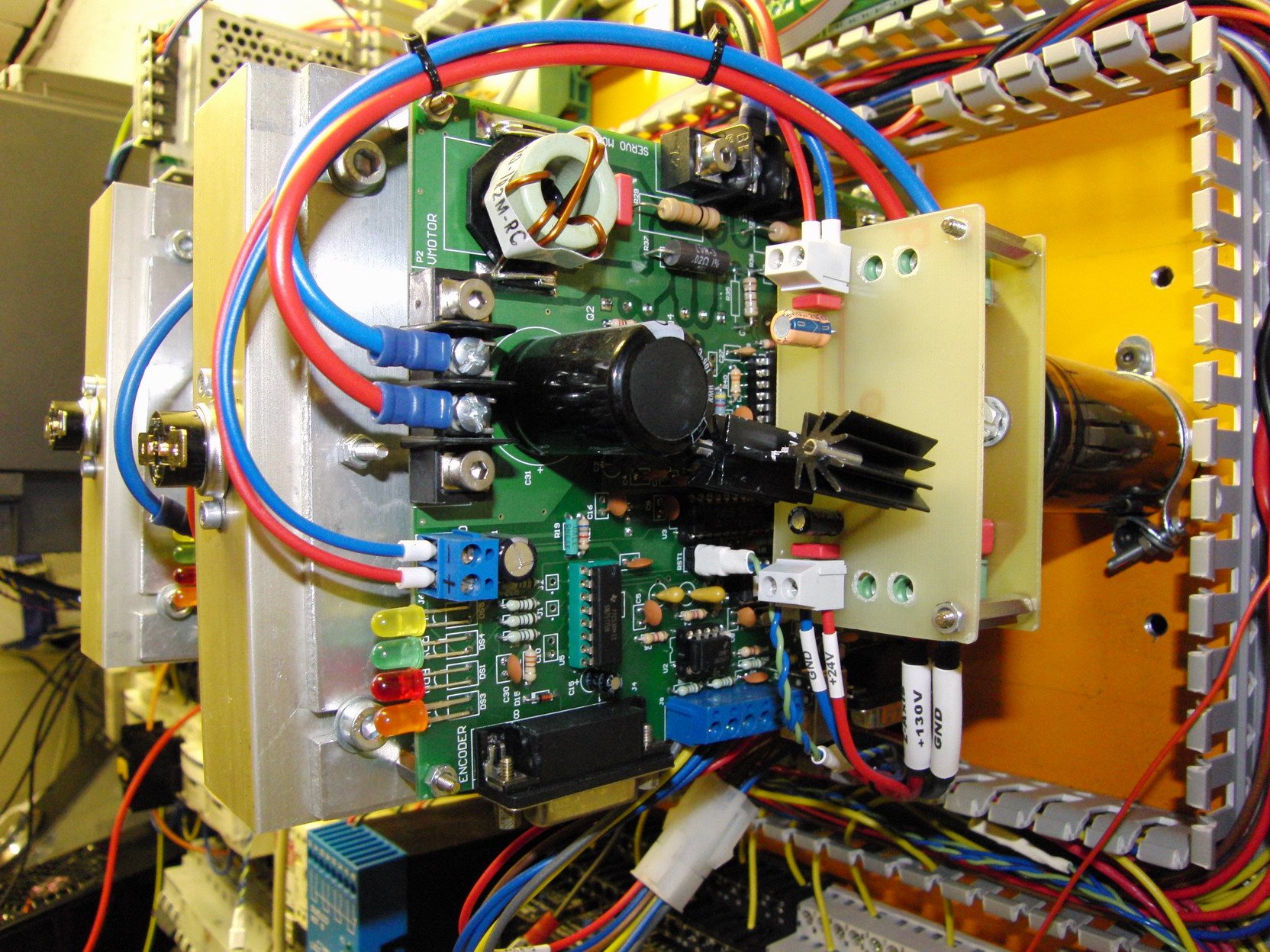
Here's a closeup of
another little board I made, or two actually. The HP-UHU
needs 15VDC for its low voltage circuits. I already had
24V and 5V powersupplies in the system and I couldn't
really find an affordable 15V switchmode supply for
DIN-rail mounting so I made a couple of PCB's with a
7815 regulator and some filtercaps. 24VDC in, 15VDC out
- works fine.
The lower one of the
two PCB is a filter for the motor power supply. The
wires between the power supply and the drives are quite
long so I wanted to put an extra filter cap as close to
the drive as I could to help the internal cap share the
ripple current. The PCB also houses a fuse with an
antiparallell diode and a MOV. The diode lets current go
from the drive to the powersupply in case the fuse blows
and the MOV together with the capacitor hopefully clamps
the voltage spike that develops when the fuse blows,
protecting the drive. I haven't had a single fuse blow
on me yet so it's still unkown if it works.
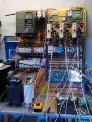
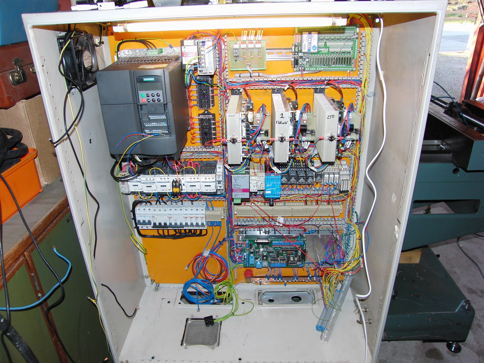
These two photos shows
pretty much the same thing. The one on the left side is
the one of the last ones I took before the panel went
back into the cabinet on the machine. I had it like that
for quite some time during testing and developement of
the control panel, PLC code etc. The right hand photo
shoes the panel mounted inside the cabinet. I installed
a fluorecent light in the top of the cabinet to make it
easier to work with it. Next step was to install the
transformer, rectifer and filter capacitors for the
motor power supply. They'll be mounted pretty much as
they are in the left photo.
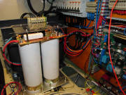 
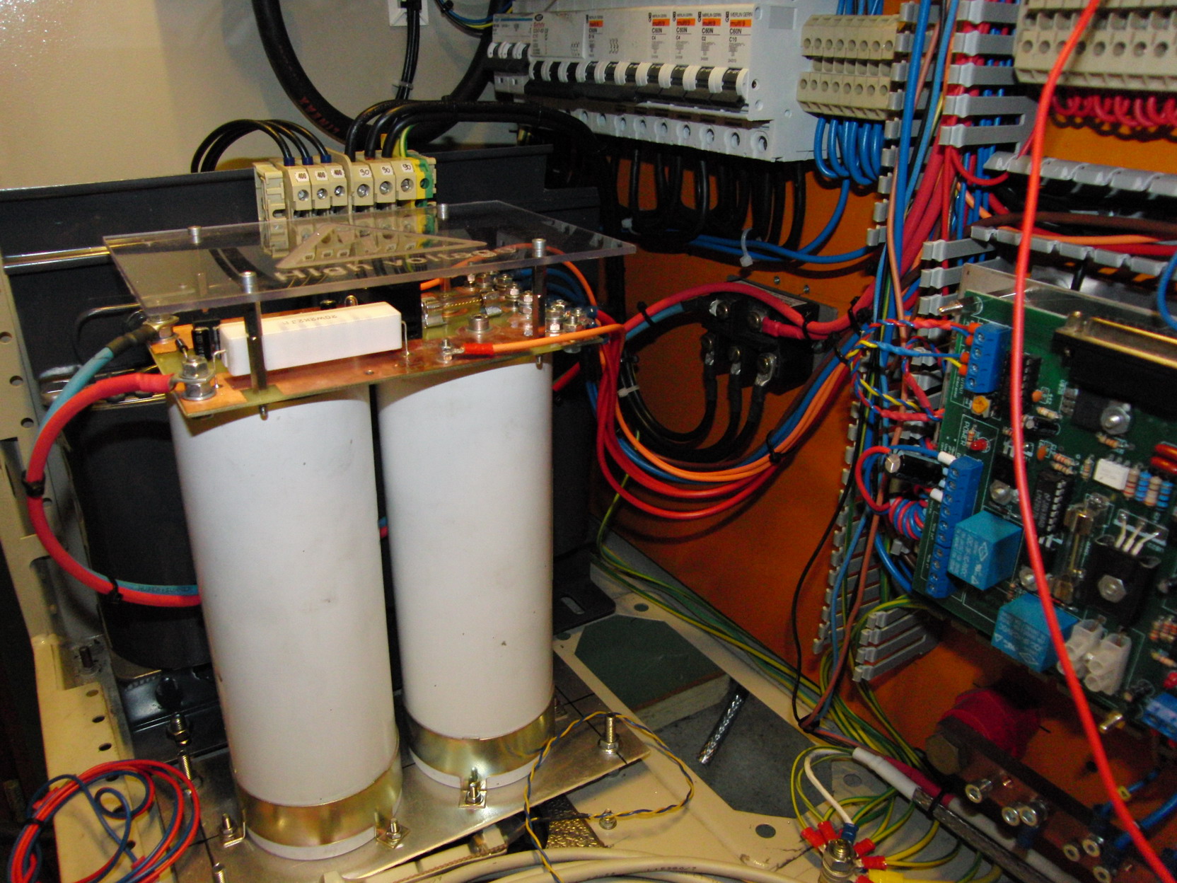
Here are two closeups.
To the left, the filtercaps and powerdumps circuit with
the transformer in the background. You can see the
three-phase rectifier mounted to the panel. I think and
hope that the panel will provide enough cooling for the
rectifier, I'll have to keep an eye on that once I start
running the machine.
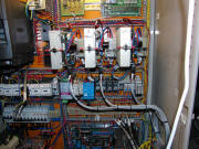
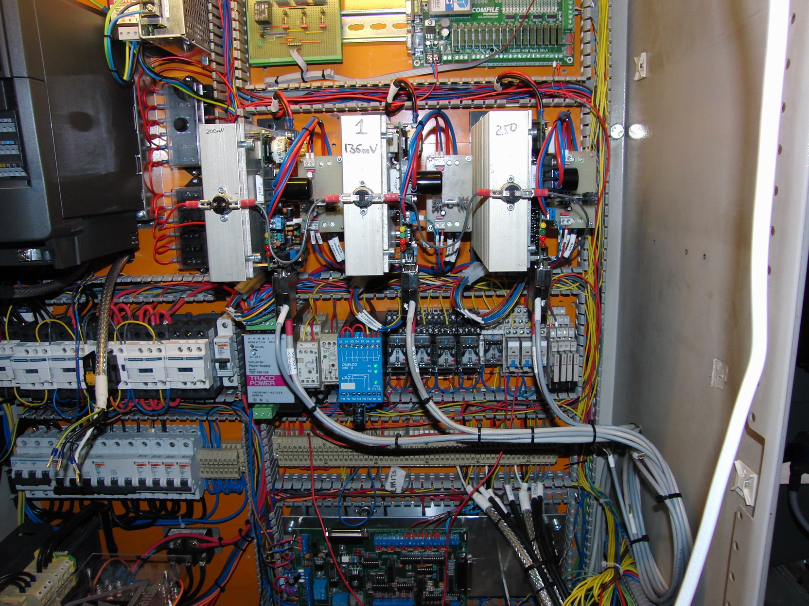
The right hand photo
shows the three servo-drives. Encoder cables coming in
at the bottom, power coming at the "front" and
motorcables going out at the top. I've mounted thermal
switches to the heatsinks, wired in the E-stop chain so
it shuts down the machine in case the heatsink
temperature goes above 60°C. The same type of switches
are mounted on the heatsink for the power resitsors and
the servo-motors have internal thermal switches. They
are all wired to separate relays and the relays are then
wired to the E-stop chain as well as to the CUBLOC PLC,
that way I can let the PLC tell Mach3 what caused the
E-stop in case it happens. Servodrive overheat,
servomotor overheat, resistorbank overheat etc.
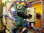
My intention is to run
this machine with a
Smoothstepper from Greg at Warp9Tech Design. This
looked like a very promising motion controller when it
was introduced but now, well after year the plugin is
still in beta and things that was promised looong ago
still doesn't work. So far thoguh it have been working
quite good during general testing and sisnce the machine
isn't really finished yet I'll just have to see what
happens. Anyway, initially I had the Smoothstepper
mounted next to the break-out-board but that din't work
very good. Every time I hit E-stop and the contactor
switched in bleeder resistor across the powersupply the
Smoothstepper locked up and lost the USB connection to
Mach3. So I decided to move it into the computer case
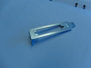
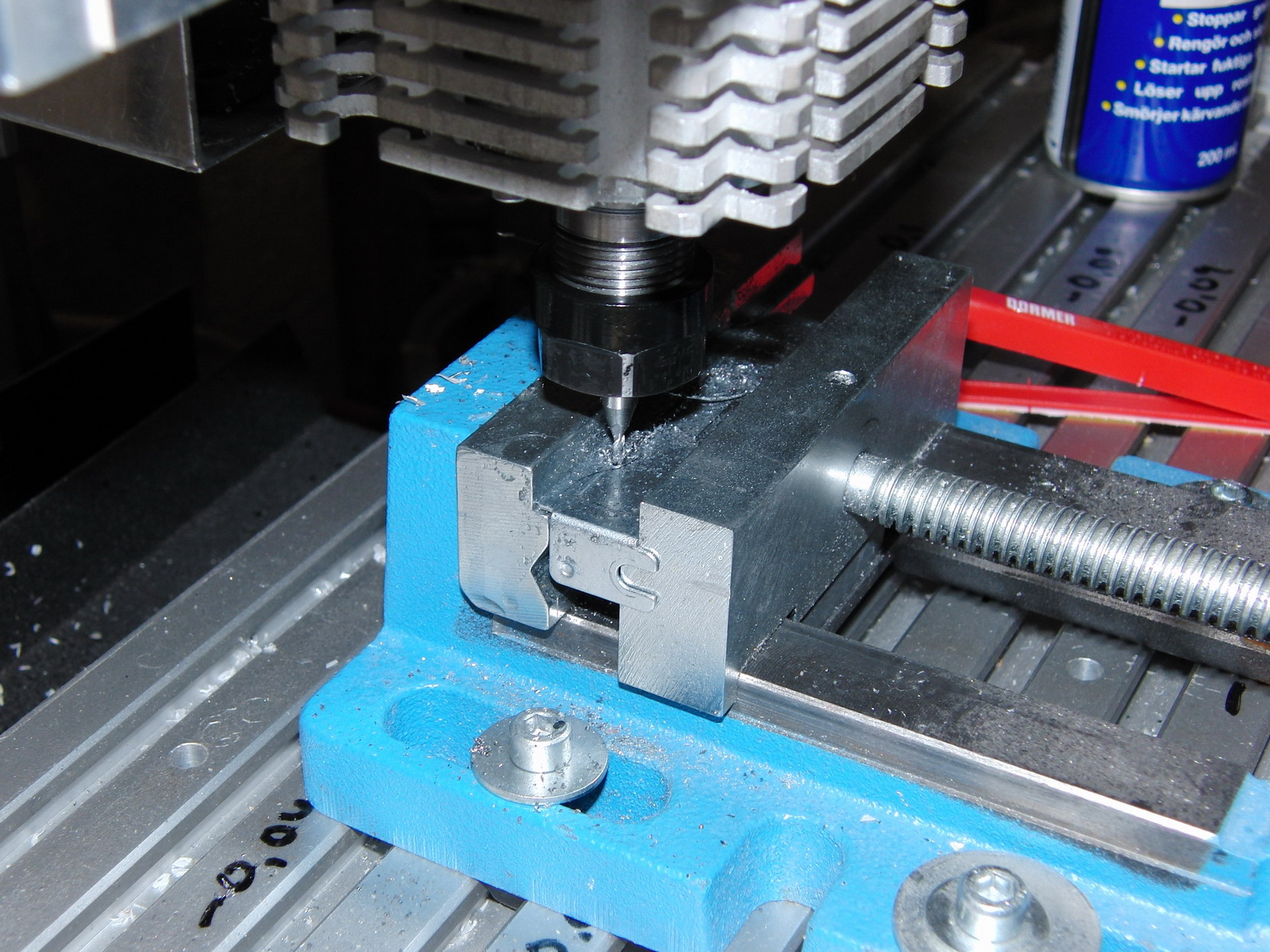
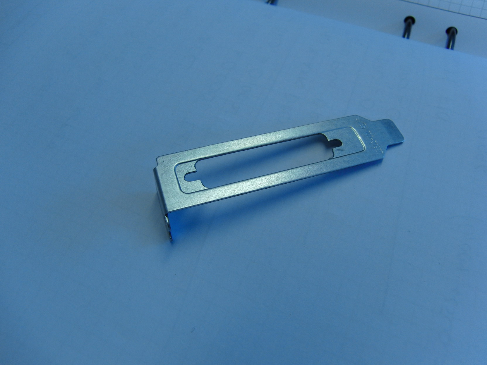
instead. The computer, by the way, will be mounted to
the inside of the cabinet door. The computercase is a
low profile type case and I couldn't find any low
profile mounting brackets for the 25-pin female
D-connectors for the Smoothsteppers so I decided to make
some cutouts in the "blank" ones that came with the case:
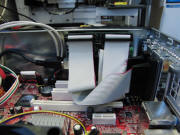
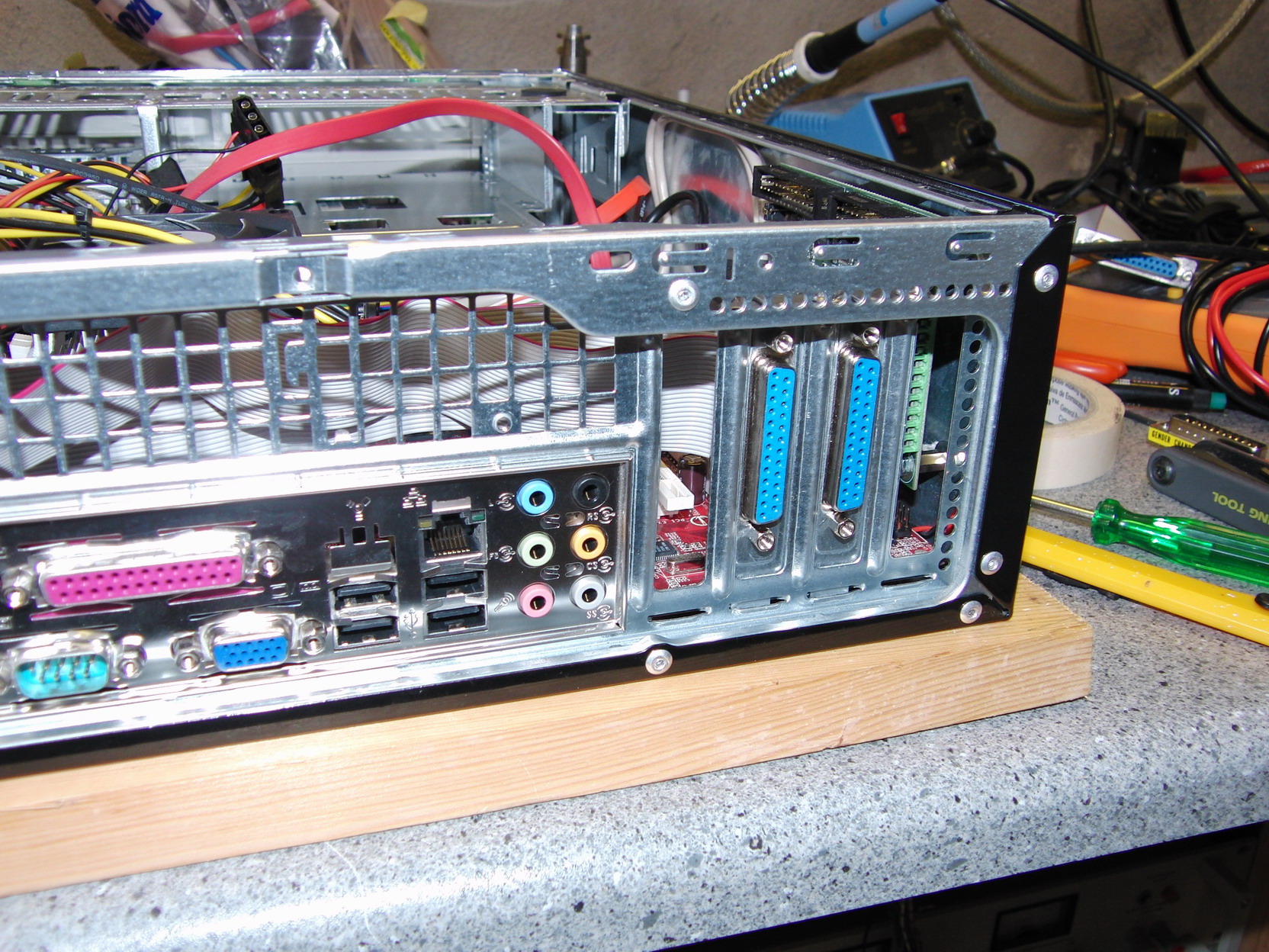
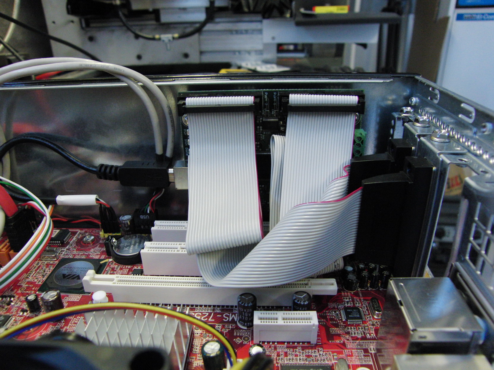
This move provided a
nice shielded place for the somewhat sensitive
Smoothstepper. I cut off a USB-cable and slodered a new
female header to it making it short and nice, right from
the USB-header on the motherboard to Smoothstepper.
More later.....
2009-09-30 |

