|
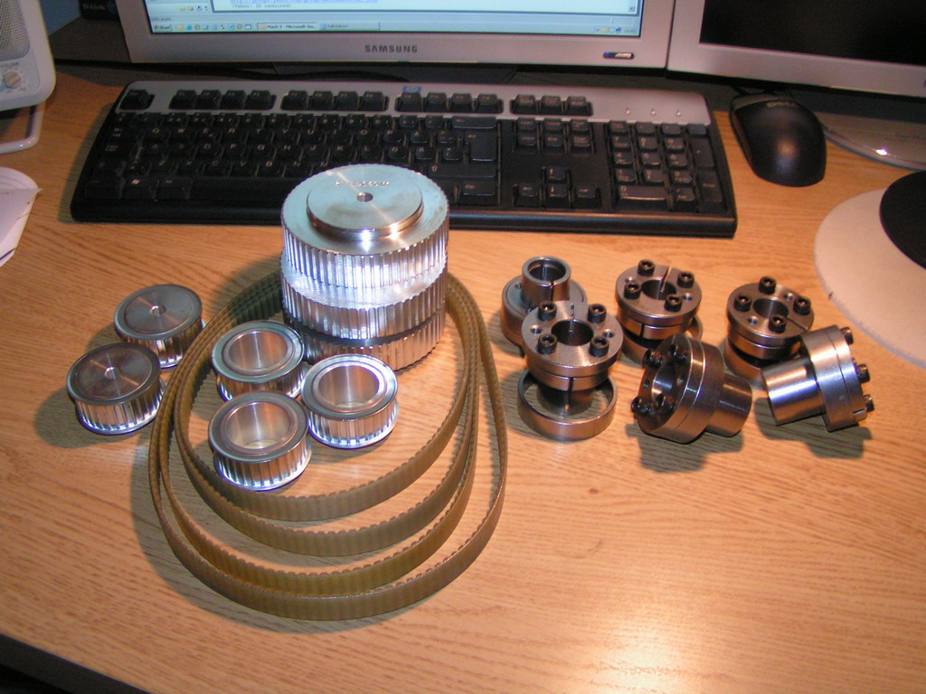
As you probably can see in
one of the first photos the mounting brackets for the servomotors
as well as the pulleys had seen better days. I'm sure
they would've worked but I just couldn't stand the way
they looked so I decided to make new ones.
I started by looking up
the various belts and pullies available. Originally the
machine was equipped with T10 belts but I settled for AT5
instead. The AT-profile is supposed to be a little
better than the T-profile when it comes to positioning
applications and although it can't transfer just as much
torque per tooth as the T-profile there will be more
teeth in contact with the pulley so I'm pretty sure it
will suffice.
I wanted a 2:1 ratio
between the motor and screw so I went for 30 teeth on
the motor and 60 on the screws. The Z-axis is a little
special, it has a 90 deg bevel gear with a 2:1 ratio but
fitting the 60 teeth pulley to the gear-shaft won't work
because it would interfere with the Y-axis sadle of the machine. So for the
Z-axis there's first a 2:1 belt-transmission, then
there's a 1:1 belt and then there's the 90 deg 2:1 gear
reduction for a total reduction of 4:1.
Here's a screenshot of the
CAD drawing for the three axes. (Sorry for the Swedish
notations in the drawing...)
With the CAD done it was
just a matter of ordering the belts, pulleys and
mounting hardware. The original pulleys were fitted with
a key but I don't have access to tooling for that so I
went for the type that clamps to the motor-shaft.
Besides, I've had bad experience with using keys in
applications like this where the axis of rotation changes direction
on a regular basis. If it's not absolutely 100% tight it
will develop a lash and once that happens i going
downhill, fast.

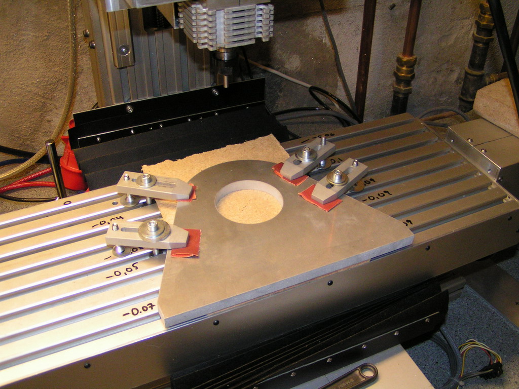
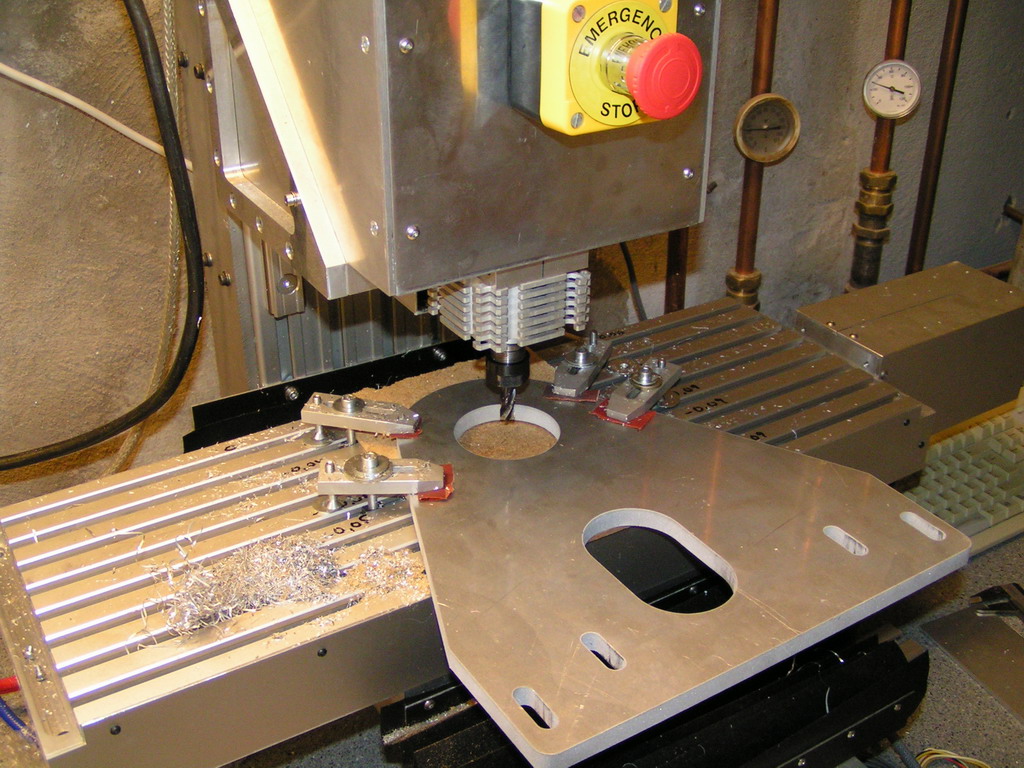
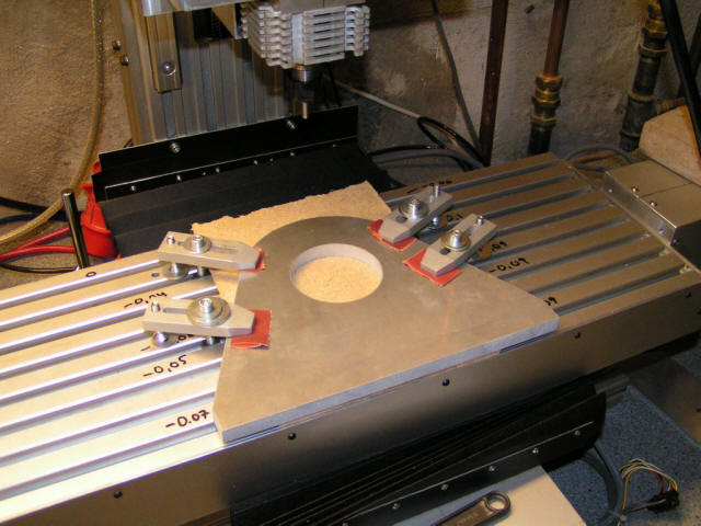
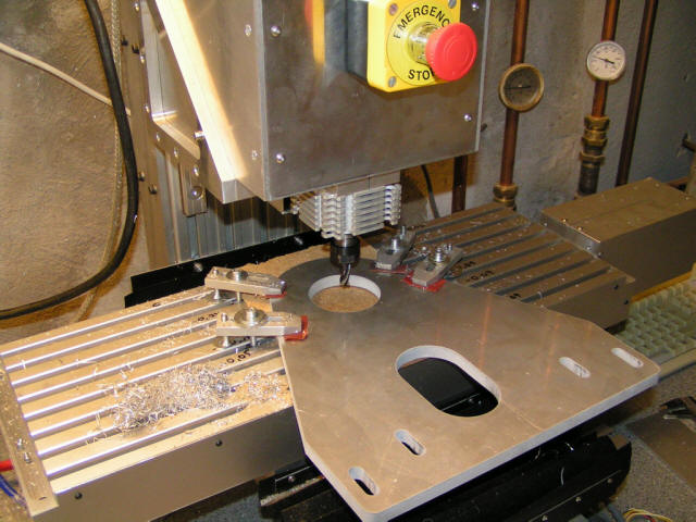
For the X- and Y-axis I
got some 12mm aluminum sheet watercut at a local shop. I
then mounted them on my small
machine in order to bore out the hole for the boss
on the servo-motor as well as drill and countersink the
holes for mounting the motor.
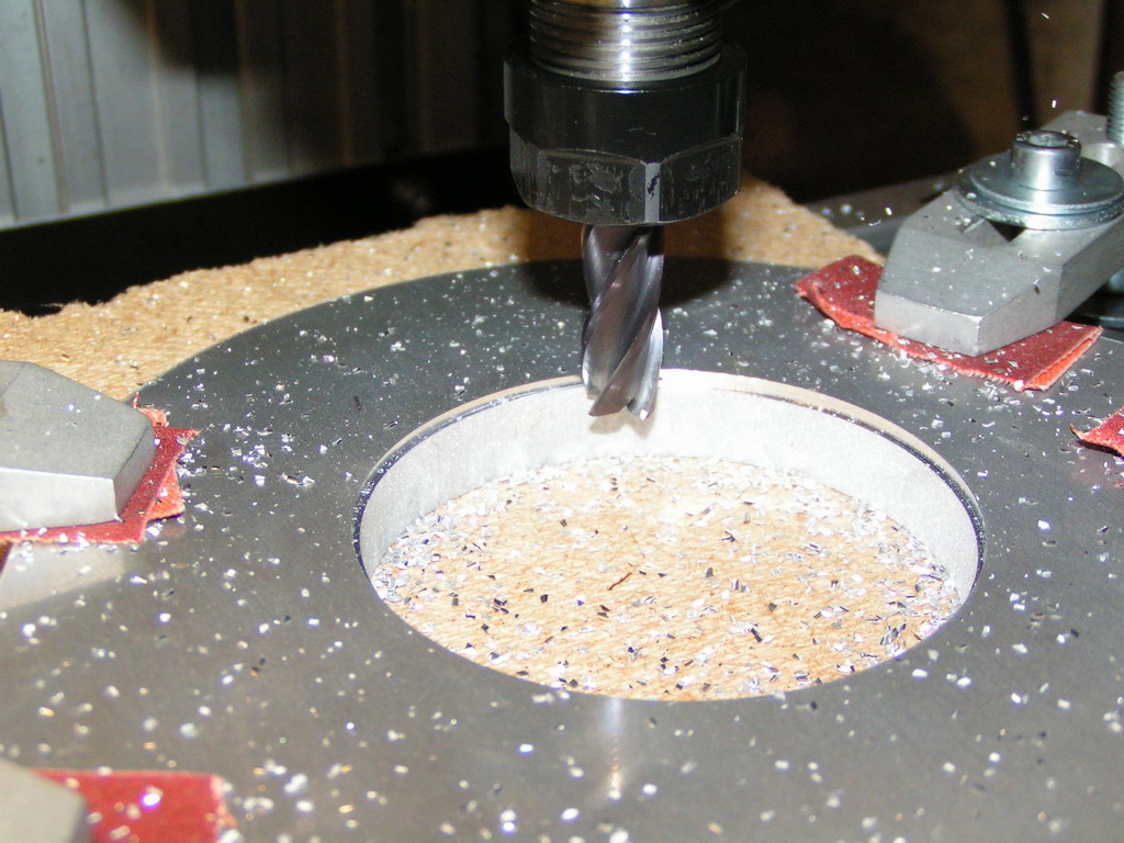
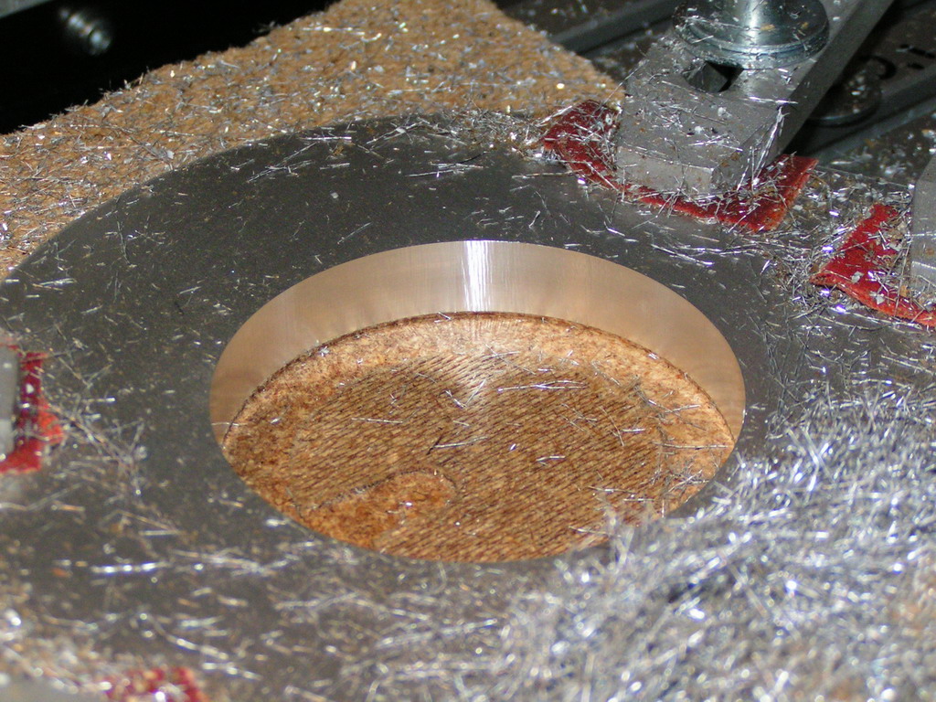
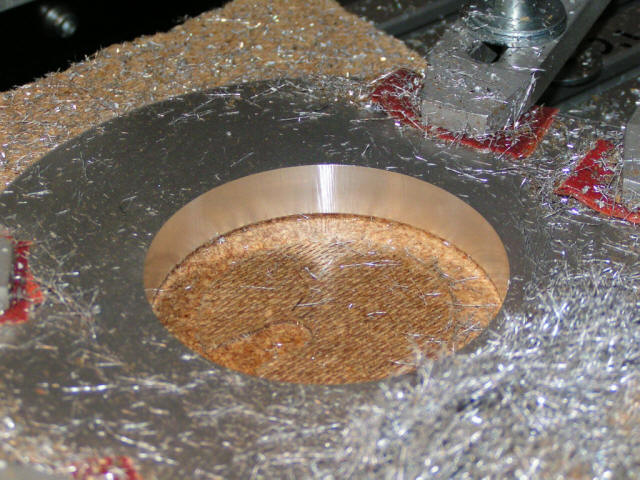
I generated a helical
toolpath and let the machine bore out the hole to final
dimension.

It turned out pretty good...
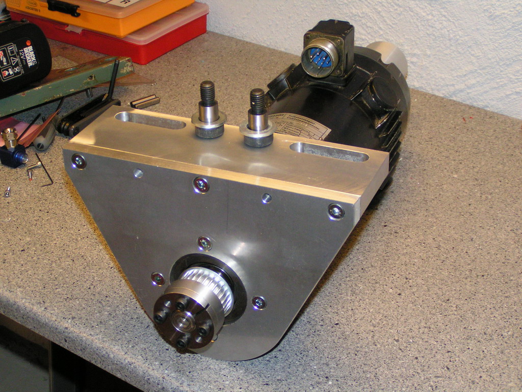
And here's the more or
less finished motor-mount for the Y-axis. The two
remaining holes are for dovel pins that will be fitted
once I know it all works out as it's supposed to.

For the X-axis I went
about the same way. Unfortunately I made a mistake while
measuring the bearing-plate on the machine to which the
motor mount will be mounted so I ended up with an extra
slot in the wrong place. It doesn't matter much but even
so I hate it when that happens.
This is the "original" but
it turned out that the four small slots shouldn't be
evenly spaced as I had drawn them...oh well.
<Back>
<Next>
|