|
I got hold of some rather
nice heavy duty aluminum extrusion that measures 90 X 180 mm and had a
fairly large center cavity that I thought would be
perfect to run the ballscrew in. All I needed to do was
to open up the top section of the extrusion thus
creating sort of a tunnel for the screw to run in. It
also had two circular cavities to use for fixing
the ballscrew bearingblocks.
 This
is actually the first picture I took while building it.
As you can see it have come quit a way already. I wish
I'd taken more photos along away the way but I was
occupied building the thing.... This
is actually the first picture I took while building it.
As you can see it have come quit a way already. I wish
I'd taken more photos along away the way but I was
occupied building the thing....
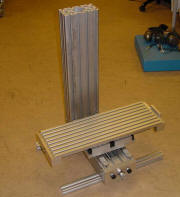
In this photo the X-axis and Y-axis
are nearly finished and work are about to start on
the Z-axis column. You can clearly see ballscrew running
in the "tunnel" of the extrusion on the Y-axis and on
the top of the Z-axis column you can see the profile of
the extrusion.

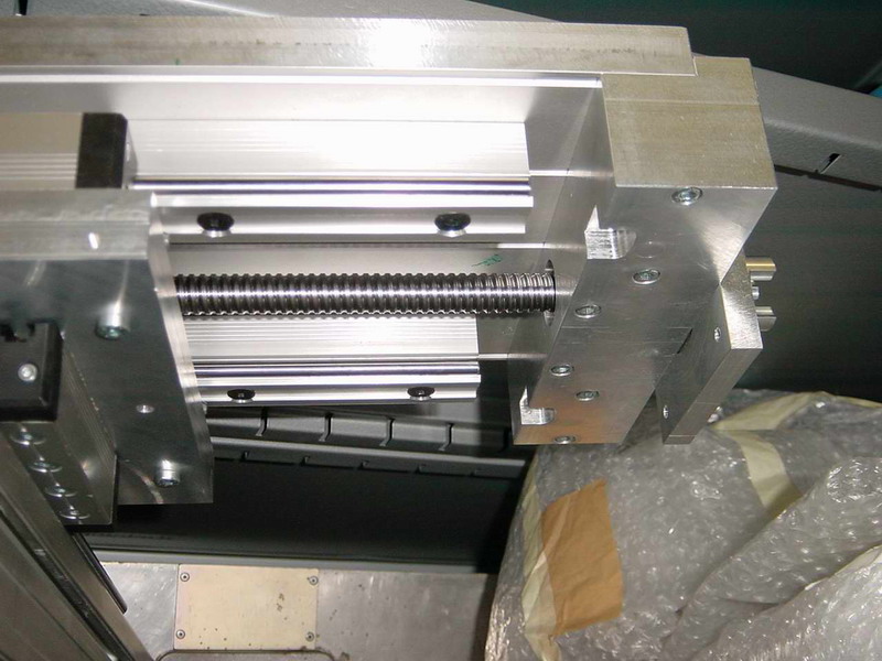
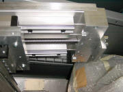
Here's a closeup of the "business-end" of the Y-axis
linear ways and ballscrew as well as the "sadle" and the
X-axis linear bearingblocks. The ballscrew (from
Isel) is hold firmly in place by two angular
contact bearings inside the aluminiumblock. The outer
races of the bearings are mounted with a spacer between
them and held in place by the flange. The inner races
are then preloaded against each other by tightening the
nut on the ballscrew (not visible in this photo). This
effectivly holds this end of the ballscrew in place. At
the time I hadn't decided what motors to use so the
block where drilled and tapped for both NEMA 23 and
NEMA34 motors.
Two aluminium plates of the same dimensions where fly
cut to make them flat. One was then drilled to be
mounted on the Y-axis bearingblocks and the other to be
mounted on the X-axis bearingblocks. The Y-axis plate (bottom
one) have slightly oversized holes lined up with
threaded holes in the X-axis plate and the plates are
fixed
together with screws. This allows the axies to be
adjusted slightly so that they are perpendicular to each other.

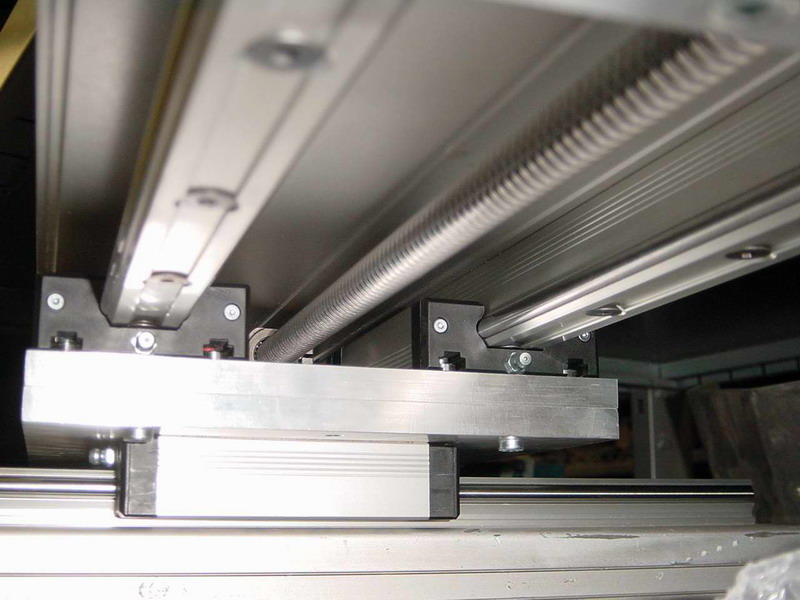
At the bottom of this picture you can see the base of
the machine, the Y-axis linear ways and bearningblocks.
Then there's the two aluminium plates, the X-axis linear blocks and it's linear ways which is screwed to
underside of the table. Running down the center of the
table is the X-axis ballscrew with it's ballnut far in
there, between the bearingblocks.
At first I intended to use one linear block per rail for
the X-axis but ended up using two. That lost me roughly
130mm of travel on that axis but it gained so much
rigidity that i decided it was worth it.
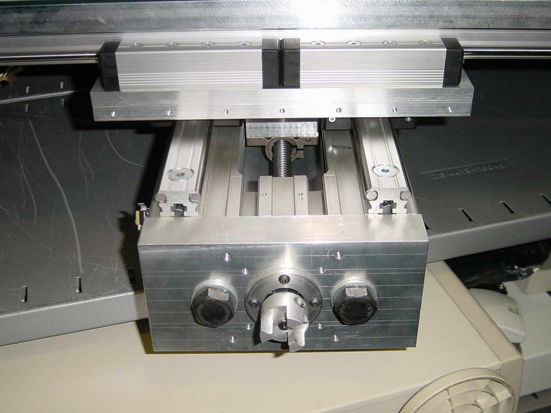
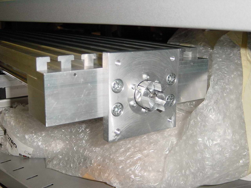
This photo shows the driven end of the Y-axis ballscrew.
A piece of 50 X 50 mm aluminium bar holds the angular
contact bearings for the screw. The bearing block is
then mounted to the table by the six M5 screws. The two
milled out sections on each side of the block is for
clearence for the linear bearings lubepoints when the
table is at it extreme end of travel.
 Here's
another view of the same piece. You can see flange
holding the angular contact bearings in place, the shaft
coupler and the mounting plate for the stepper motor.
Also visible is the T-slots on the table. The small
holes on the side, just below the table were intended
for screws to further fix the block in position to
the table but it turned out not needed in the end. Here's
another view of the same piece. You can see flange
holding the angular contact bearings in place, the shaft
coupler and the mounting plate for the stepper motor.
Also visible is the T-slots on the table. The small
holes on the side, just below the table were intended
for screws to further fix the block in position to
the table but it turned out not needed in the end.
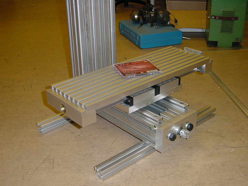
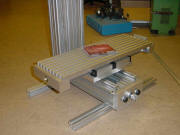 This
is an overview of the base, X and Y axis and table. With
a CD cover for size comparation. This
is an overview of the base, X and Y axis and table. With
a CD cover for size comparation.
 The
Z-axis is constructed in the same way as the Y-axis.
Except that the lower end of the ballscrew is hold in a
bearingblock which is just tightly pressed into the
cavity of the aluminium extrusion. The
Z-axis is constructed in the same way as the Y-axis.
Except that the lower end of the ballscrew is hold in a
bearingblock which is just tightly pressed into the
cavity of the aluminium extrusion.
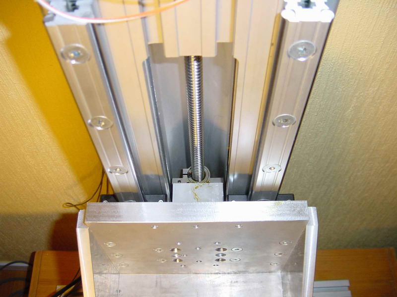
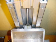
This picture shows the Z-axis viewed from the top down.
You can see the linear rails and blocks, the ballscrew
and nut and the spacerblock that attaches the nut to the
actual Z-axis.
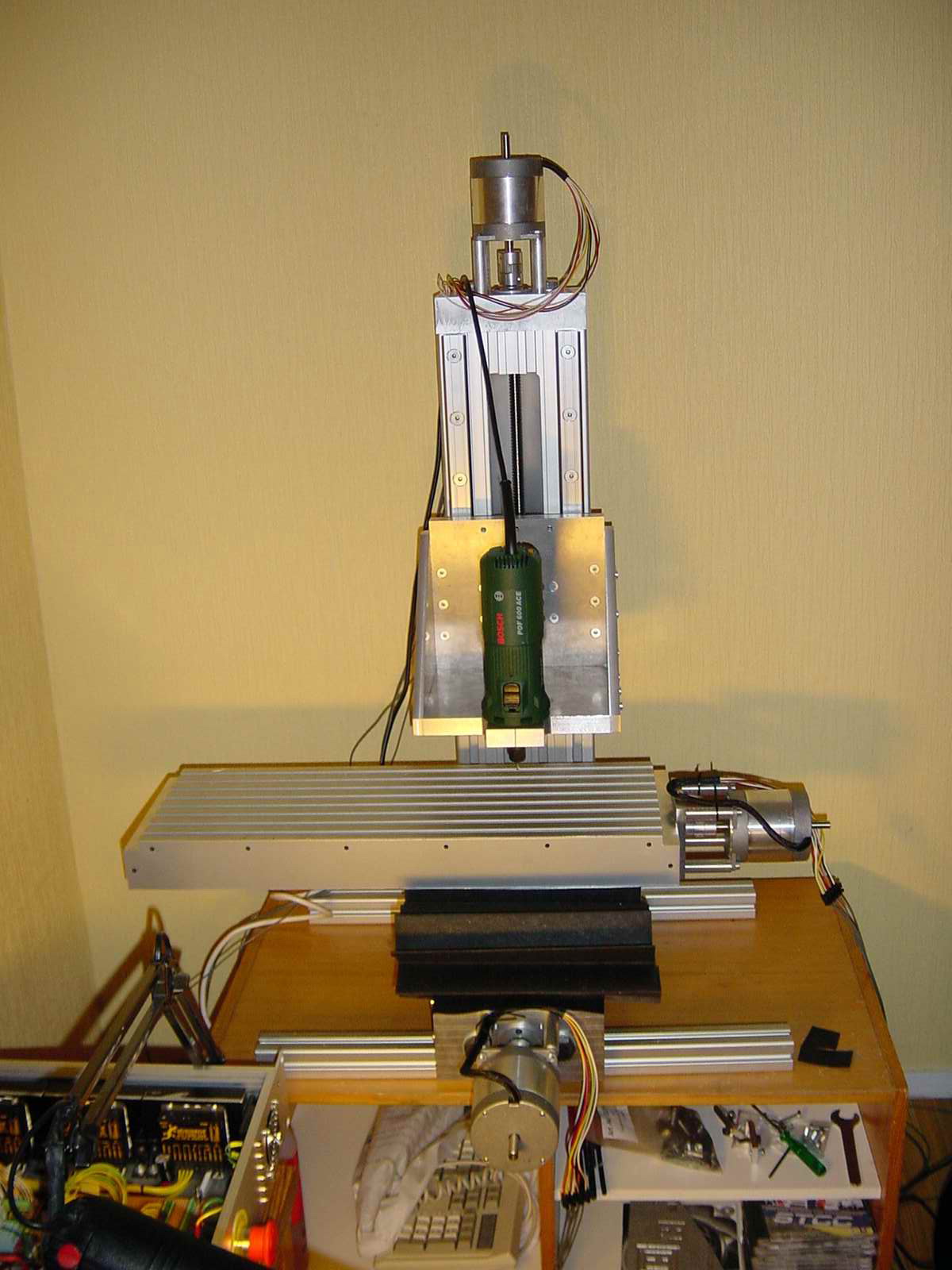
 Here's
an overview of the machine as it looked when the
initial testing begun. The spindle in the picture is a
Bosch 600W router but it has since been replaced by an
ER16 collet spindle and 3-phase motor with VFD-control.
In the lower left corner you can see part of the
electronics cabinet and if you look closely you can see
the three wonderfull G210's. You can find out more about
the electronics here. Here's
an overview of the machine as it looked when the
initial testing begun. The spindle in the picture is a
Bosch 600W router but it has since been replaced by an
ER16 collet spindle and 3-phase motor with VFD-control.
In the lower left corner you can see part of the
electronics cabinet and if you look closely you can see
the three wonderfull G210's. You can find out more about
the electronics here.
<BACK>
<NEXT>
|