|
Here we'll take a quick
look at how to set up Mach3 to use the
MiniMODBUS board described elsewhere on this
site.
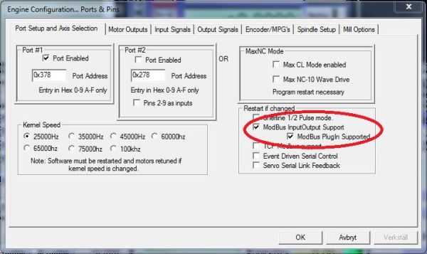
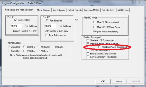
First order of business is
to enable MODBUS communcation within Mach. This is done
under Config->Ports & Pins:
Basically there are two
different ways to handle the MODBUS interface in Mach3 -
the old one and the new. The old interface is pretty straight forward for things like normal inputs and
outputs but for analog I/O it gets a bit
more complicated. The new interface is a bit more
flexible but it comes at a price of a higher overall
complexity. I tend to use
to new interface which is what we're going to look at
here but if you prefer to use the old interface have a
look at the bottom of this page for a very brief walk
thru.
The new interface is enabled by ticking the second
checkbox labeled ModBus PlugIn Supported circled
in red in the
above screenshot.
Now Mach3 is "MODBUS-aware"
and we can start configuring it for our intended
purposes. I thought that for this basic setup we'll do
the following:
-
1 Digital input mapped
to the CycleStart button
-
1 Analog input mapped
to the Feedrate overide
-
2 Digital outputs
mapped to the spindle control signals for CW and CCW
control.
-
1 Analog output mapped
to the spindle speed (controlled by the S word)
The above will demonstrate
the use of the available inputs and outputs on the Mini
MODBUS board and can easily be changed or expanded as
needed.
To set this up we first
need to go to Function Cfg's -> Setup Serial ModBus
control. This brings up the MODBUS configuration
window which is where we tell Mach3 how to access the
device, what registers to read and write and at what
adresses in the device those registers are. But before
we start the configuration we should perform a quick
test to verify that the communication is OK. This is
easily done by clicking the Test Modbus button in
the upper right hand corner of the configuration window.
Doing so brings up the following dialog:
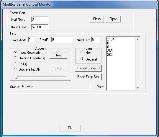
Make sure you select the
correct COM port as well as the baudrate you have set on
the Mini MODBUS board, the default is 57600, then click
Open. Hopefully you'll see the message No
error in the Status field.
If you look at the
register definitions for the Mini MODBUS board you'll
see that there are 5 input registers available, starting
at adress 0. For our test we're going to read those 5
input registers.
Enter the Slave adress
of the Mini MODBUS board (most likely 1), start adress
of 0 (because we want to start reading at the first
register), enter the number of registers to read (5) and
tick the Input Register(s) radio button, tick the
Decimal radio button and finally click the Read button.
If everything works as it should the box will be
populated with the values contained in the 5 input
registers. The two values at the bottom are the message
counters and these should both increment by 1 each time
you press the Read button.
If you want you can try
changing the slave adress and click the read button
again. Because there is no slave with that adress
available you'll get a Receive timeout which is
exactly as expected. If you now revert to the correct
slave adress and click read again you'll see that the
values of the two counters no longer match. This is
because the first counter shows how many valid MODBUS
messages the slave has detected and the second counter
shows how many of those messages the slave has
responded to. It does not respond to messages not
adressed to it.
If that works out OK
you're all set - close the port and click OK to get rid
of the MODBUS test dialog.
Now it's time to tell
Mach3 which register we want to access and "where" they
are:
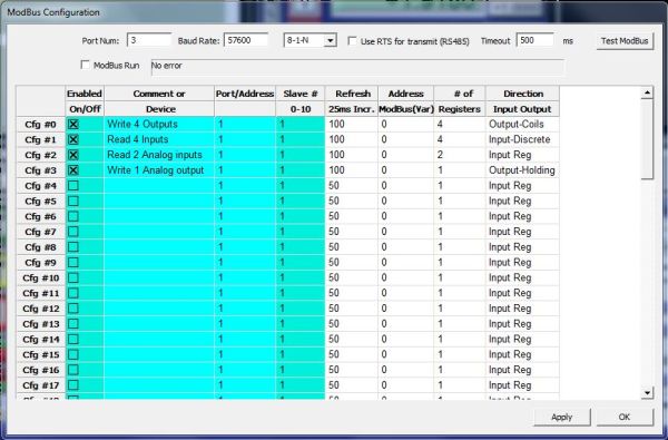
With the above setup the
four outputs on the board is controlled thru the MODBUS
Configuration 0 buffer. The four inputs are read from the device and put in MODBUS Configuration buffer 1, the 2
analog inputs are read from the device and their values
are put in MODBUS configuration buffer 2 and finally the
analog output is controlled thru MODBUS Configuration
buffer 3.
What does all this mean?
It means that when Mach3, for example, sets an output
that we have mapped to our MODBUS device it actually
sets a bit in the MODBUS configuration buffer (Cfg#0 in
this case). The content of this buffer is then
transfered to the device at the specified interval. When
Mach3 reads an input that we've mapped to our MODBUS
device it actually reads the MODBUS configuration buffer
in memory (Cfg#1) in this case. The content of this
buffer is updated with the state of the physical inputs
at the interval we specify.
Make sure you set the
correct Port number, baudrate and communication
parameters, tick the ModBus Run checkbox and then click
Apply. Hopefully the LED next to Analog Input 1 on the
board start to blink which indicates it is receiving
MODBUS messages.
At this point all the
information we need is transfered to and from the Mini
MODBUS board. Now we just need a way to take control
over it.
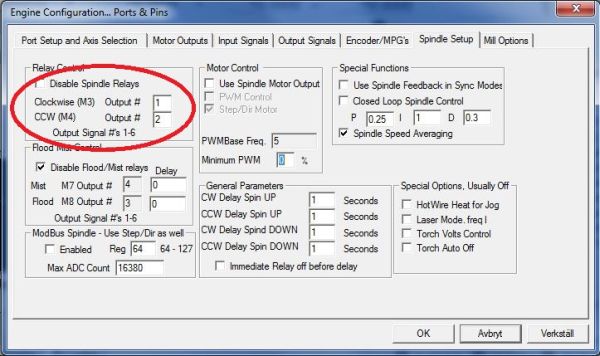
Close the MODBUS
configuration dialog (the LED should continue blinking).
Select Config -> Ports & Pins and go to the
Spindle Setup tab. Here we tell Mach3 that when the
spindle is supposed to turn CW we want Output 1 to be ON
when it's supposed to turn CCW we want Output 2 to be
ON. Please note that this is NOT the outputs on our
MODBUS board - these are yet just "signals" that
we need to map to the device we want which could be the
LPT-port or as in this case the MODBUS device.
Now, when M3 is executed
the signal Output 1 will go "ON" and when M4 is executed
the signal Output 2 will go "ON". Now, we'll map these
signals
to the physical outputs on the Mini MODBUS device - this
is done thru what's called a BRAIN which is kind of like
a little PLC ladder program.
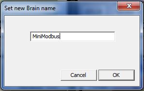
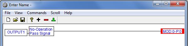
In Mach3, select Operator
-> Brain Editor and give the newly created BRAIN a
suitable name:
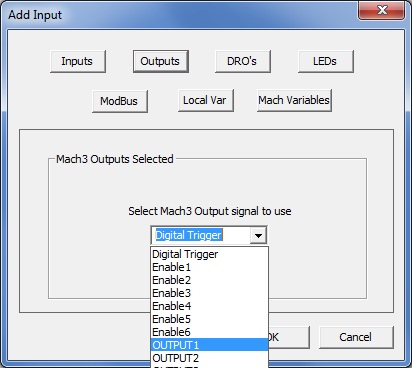
In the BRAIN editor we'll
start with getting the two output signals mapped to two
of the physical outputs on the board. Click on the
little black plus-sign in the toolbar to add an entity
to the BRAIN, click on the Outputs button and in the
drop-down list select Output 1 and click OK.
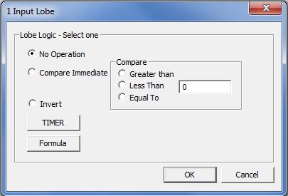
Now select the newly added
item on the screen and once again click on the
plus-button. This will bring up a 1 input lobe selection
dialog where we can choose what we want to do with this
sigal. Since we don't want to modify it any way we
select the No Operation radio button and click OK.
Again select the newly
added entity (the NoOperation) on the screen and click the little
green thing looking like an upside down version of the letter T.
This is what is called a termination which is how we
specify where the "output" of the previous
operation (NoOperation in this case) is going - which in this case is to one of the MODBUS
configuration buffers.
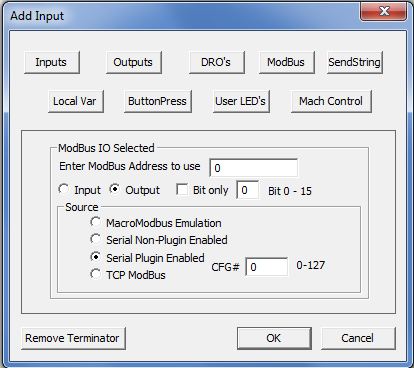
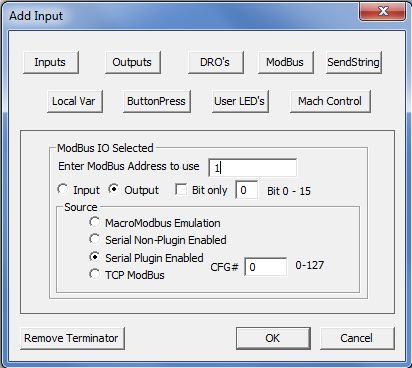
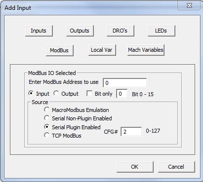
Since we previously set
up Cfg#0 to write our 4 outputs this is where we want our
"signal" to end up. Click on the MODBUS button and tick
the Output radio button. Modbus adress should be 0
because we want to access the first entity in the buffer.
Make sure that the CFG# textbox is set to to correct Cfg#
(0 in this case) and select the Serial Plugin Enabled
radio button.
At this point the BRAIN
should look something like this:
Now repeat the process for
Output 2 but this time put the value 1 in the Modbus
Address to use text box in order to access the second
entity in the buffer.
That's it for the two
digital outputs. The analog output on the board is going
to control the speed of our spindle so we need to get
the desired spindle rpm from Mach3 and out to our board.
For this example I'm assuming that we have a spindle
speed range of 0-5000 where 0 rpm requires 0V from the
analog output and 5000 rpm requires 10V from the analog
output.
Add a new entity to the
BRAIN, select the DRO's button and look for DRO202 -
Spindle RPM overdn. This will get the desired
spindle speed with any potential override factored in.
Since our max spindle speed is 5000 and the maximum
value we can write to the analog output register is 1000 we
must scale the "raw" RPM value down before writing it to the
MODBUS configuration buffer. This is done with the
formula function but for some reason (don't ask me) it doesn't work if
we don't first run the "signal" thru a NoOperation like
we did with the output signals. So, first add a
NoOperation then select it and add a Formula operation
by clicking the Formula button in the One Input Lobe
dialog.
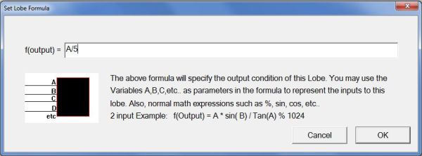
This is a simple matter of
dividing our 0-5000 rpm value by 5 to get a 0-1000 value
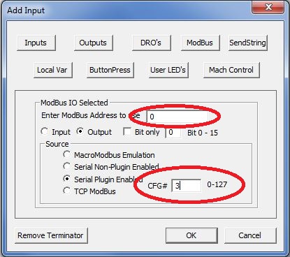
that we can send to the board. Now we can terminate the
signal to the correct MODBUS Cfg# which in this case is
Cfg#3 since that is what we set up to write to the
Holding Register controlling the analog output. In Cfg#3
we want to access the first entity (we only have one but
anyway) so we put a 0 in the ModBus Address to use
text box.
At this point it might be
worth mentioning that, as you've probably noticed, the
Modbus Adress to use entry has nothing to do with
the actual adress of the register in the device (the
miniMODBUS in this case), it's simply which "location"
in the selected MODBUS Cfg# buffer that Mach3 acesses.
The MODBUS "engine" then trasnferes this to and from the
device based on the information setup in the MODBUS
configuration dialog.
OK, that was all the signals going from Mach3 to the MODBUS device. Now it's time
tackle the signals going the other way. We're doing one
analog signal for the feedrate override and one digital
signal for the Cycle Start button. Lets start with the
feedrate override.
The process is just as
before but this time we need to get our "input"
from the MODBUS buffers and write it to Mach3 instead of
the other way around. We start with adding a MODBUS input to
the BRAIN, since we've setup Cfg#2 to read the registers
containing the values of the analog inputs we select Cfg#2 and since we want the first register of the two we
select Address 0.
Now, the value from the
analog input ranges from 0 to 4095 which is way too much for feeding
directly to the feedrate override DRO in Mach3 (we don't
want a feedrate override of 4000%) - we need
to scale this down conciderably. Add a NoOperation and
then a Formula function. I went for a ratio of 1/35 to bring the final value down to 0-117% but you can
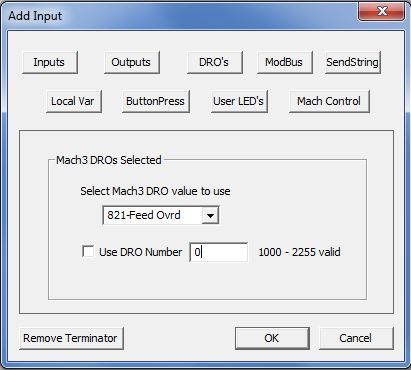
obviously select whatever you want. Finally we terminate
the signal to a DRO which in this case should be
DRO821 - Feed ovrd.
Finally lets do the Cycle
Start button. This is going to come from digital input
number 0 on the board and we've set up the MODBUS configuration to read
the digital inputs into Cfg#1 so we add a MODBUS input
with those settings to the BRAIN. We run the "signal"
thru a NoOperation and then terminate it to a ButtonPress where we select the Cycle Start button in
the drop down list.
At this point the BRAIN is
complete and should look something like this:
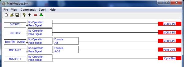
You can
download the finished BRAIN here if you want.
Now save the BRAIN and
exit the editor. Then select Operator -> Brain
Control and click the Reload all Brains
button - you should now see your BRAIN in the list.
Select it, enable it by ticking the Enables checkbox and
then click the View Brain button. This shows your newly
created BRAIN "live" where you can see what is
happening with the various signals:
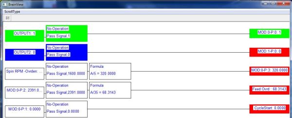
Here we can see that
Output 1 is ON (because I commanded M3), the commanded
spindle RPM is 1600 which is divided by 5 (=320) and written to
the board thru entity 0 in Cfg#3. The value 2391 comes in
thru entity 0 in Cfg#2 (which is our analog input 0) and is then
divided by 35 before going to the Feedrate override DRO
(68%). Finally we have our digital input "feeding" the
Cycle Start button which in this case is OFF.
A quick look at the old
style interface.
At first impression the
MODBUS interface discussed above can look quite
complicated. There is another way to handle it which is
to use the old interface - it isn't quite as flexible as
the new interface but it works and it maps the inputs
and outputs of the MODBUS device to Port 0 so you can
use the normal Ports and Pins dialog to map your signals
to the physical inputs and outputs on the board. It gets
a bit trickier with the analog signals but we'll look at
those to at the very end.
To use the old interface
simply leave the Modbus PlugIn supported checkbox
unticked:
Now when you select
Function Cfg's -> Setup serial Modbus control you
get the setup dialog for the old style interface instead
of the new one:
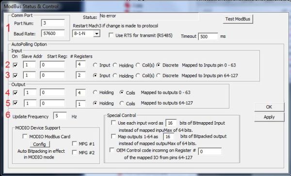
I think this dialog is
pretty straight forward but I'll do a quick run thru on
the above settings as they match the MiniMODBUS board.
1) This is where
you set the communication parameters, make sure they
match those of the MiniMODBUS board. Pressing the Test
ModBus button brings up the same test dialog as in the
new interface shown above so take a look there for
details.
2) Here we setup
the first series of inputs to be read from our device
and into Mach3. From left to right: Slave adress is 1,
we want to start reading at adress 0, we want to read 4
registers and the type of registers to read are discrete
inputs. These will then automagically be mapped to Port
0, pins 0-3
3) This is the
second set of inputs to be read from our device. From
left to right. Slave adress 1, start at regsiter 0, read
2 register of type Input register. These will end up as
16-bit values at port 0, "pins" 0 and 1 (more about that
later).
4) This is the
first set of outputs. Slave adress 1, start at adress 0
and write 4 registers of type Coil. The value written to
the coils will be taken from Port 0, pins 0-3.
5) This is the
second set of outputs. Slave adress 1, start at adress 0
and write 1 register of type Holding. The value written
to this register will be taken from port 0, "pin" 64
6) This setting
controls how many times per second the transaction of
information between Mach3 and the MODBUS device takes
place. Obviosuly there's an upper limit to this setting
and setting it higher than neccessary is not recommended.
Really, 10Hz or there abouts should be more than enough.
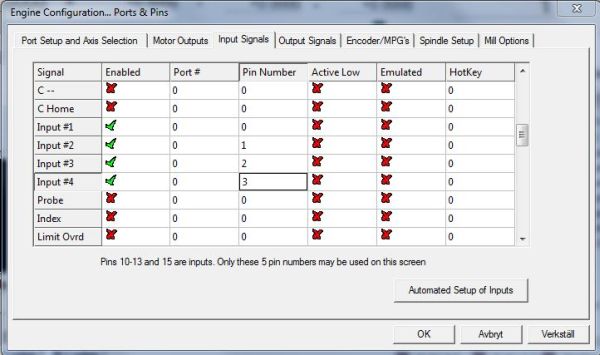
At this point the four
digital inputs and four digital outputs are mapped to
pins at the "virtual" port 0 and can be accessed as pins
on your normal LPT-port by setting them up in the Ports
& Pins dialog:
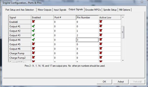
Note that Port# is set to
0.
Here I've simply mapped
the I/O's on the MiniMODBUS to Input #1-4 and Output
#1-4 respectively but you can of course use any signal
you want. Just be aware that mapping things like home-
and limitswitched to MODBUS I/O is not recommended due
to the apparent delay in transfering the data from the
board to Mach3. When using the LPT-port each input is
read 25000 times per second or more (the kernel
frequency) while when using MODBUS you can't expect to
have the state of input transfered to Mach3 more than
perhaps 25 times per second.
At first it may seem odd
that we have our inputs mapped to same pins as our
outputs - something that would indeed create a problem
if we did this with the LPT-port but in this case it
is how it works.
OK, so how about those
analog signals? Well, to access those we have to resort
to a little bit of macro programming. I won't go
into much details here but I'll show you the commands
needed to access them.
The following will get the
value of analog input 0 and display it in a message box:
MsgBox("The
value on Analog 0 is: " & GetInput(64))
The following will write
the value contained in DRO202 (Desired spindlespeed
including override) to the analog output register. As in
the BRAIN example with the new interface we divide the
value by 5 before writing it to analog output register.
Dim AN_0 As Integer
AN_0 = GetOEMDRO(202) / 5
SetMODOutput(64, AN_0)
Got any questions or
comments? You can contact me at
henrik[at]henriksplace[dot]se
Henrik Olsson 2011-08-13 |