|
On this
page I'll give you all the details needed to build your
own PIC based MODBUS RTU slave board to be used with the
Mach3 CNC control application or any other application/device
acting as a MODBUS master. The hardware itself can
obviosuly be used for any application you see fit but
the firmware supplied on this page makes into a MODBUS
RTU slave device.
Here's a
list of the hardware features of the board:
-
4
digital inputs, opto-isolated, with LED indicator.
-
4
digital outputs, open collector, 500mA, LED
indicator, protection diode.
-
2
analog inputs, 0-5V, 10bit resolution.
-
1
analog output, 0-10V, 10mV resolution, 50mA drive
capabillity.
-
Wide
operating voltage range, 15-30V
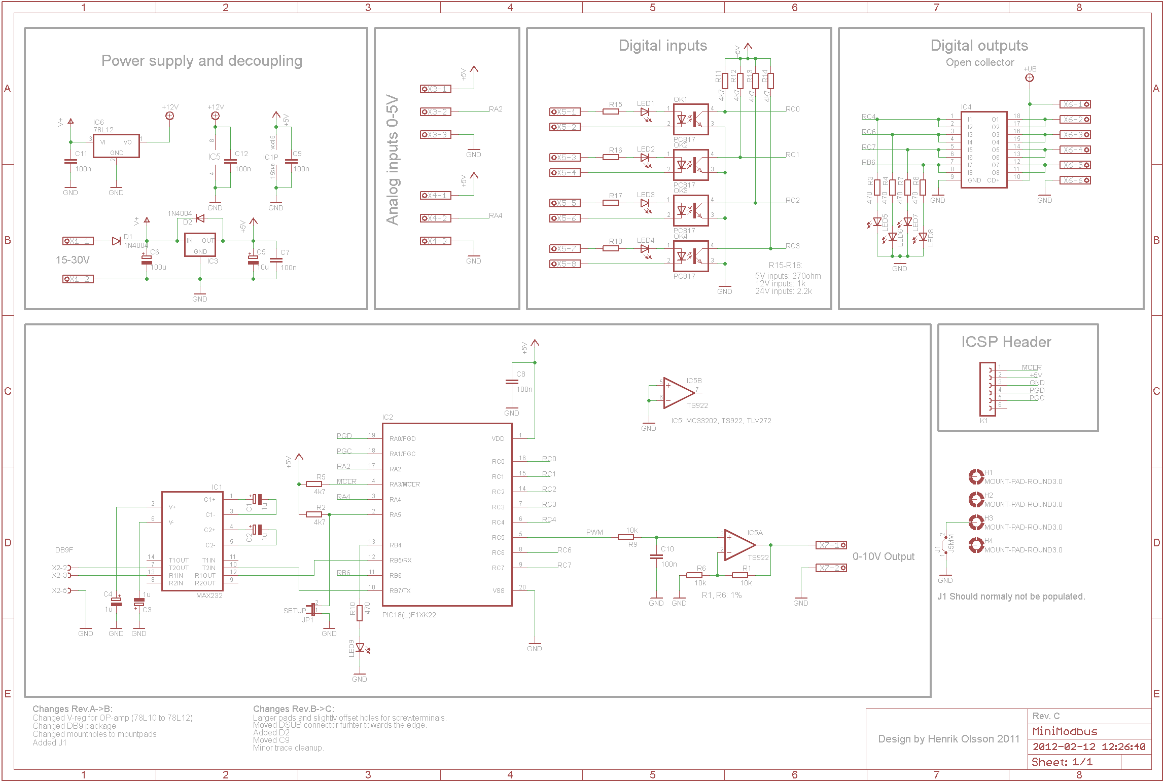
The
schematic:
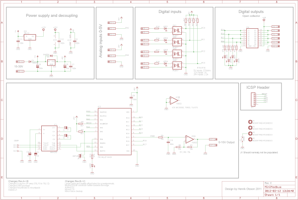
Click on the picture for a
high resolution version or download as .pdf
When it comes to the
hardware there's really nothing special going on. Your
typical linear voltage regulator, standard PIC circuit
operating from its internal oscillator, MAX232 level
translator for the RS232 interface, PC817 opto isolators
for the inputs, ULN2803 for the outputs and a
rail-to-rail OP for the analog output - that's pretty
much it.
As you can see I've
brought out both legs of the LEDs in the opto-isolators
to the connectors. This provides the highest
flexibillity when it comes to interfacing various
sensors etc. The value of the series resistors (R15-R18) can be
choosen to properly match any desired input voltage.
The ULN2803 darlington
driver used to drive the outputs contains 8 drivers,
each capable of sinking 500mA. Since the board only has
4 outputs I've connected two drivers in parallell for
each output. Even so I'd try to stay around a maximum
current of 500mA.
The two analog inputs are
wired straight from the connector to the PICs analog
input, the maximum input voltage is 5V. If, for example,
0-10 input range is desired an external voltage divider
must be used.
The analog output is
driven by the PICs ECCP module feeding an 8kHz PWM
signal thru a low-pass filter and then thru an amplifier
with a gain of 2. This makes the analog output 0-10V.
It's not super accurate and/or ultra linear but for a
cheap board like this I think it's good enough.
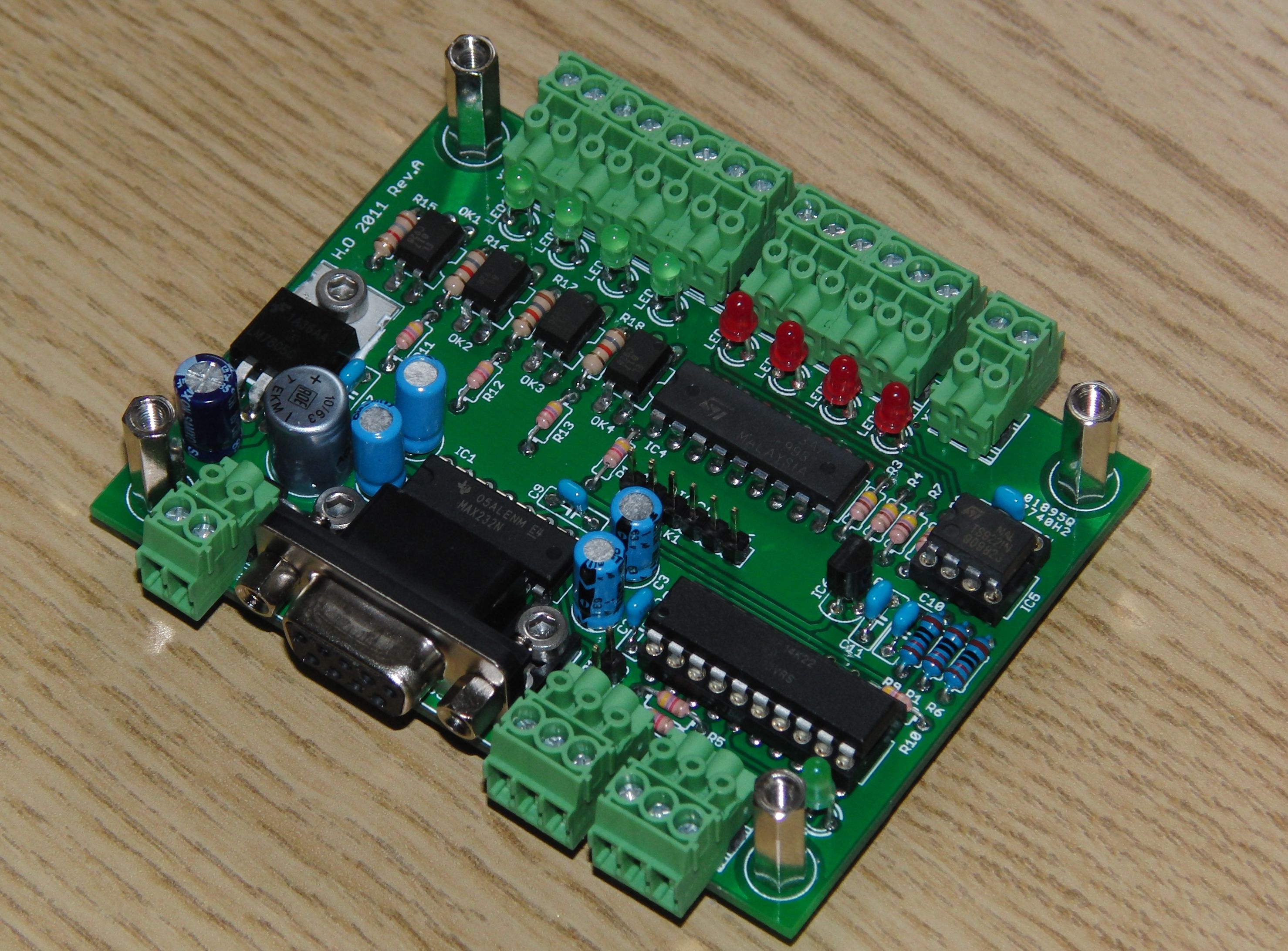
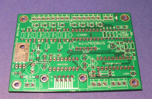
The board (86x65mm):
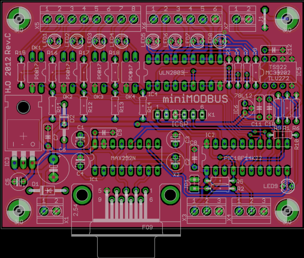

Click on the pictures for
larger version.
(The photo of the board shows Rev.A while the screenshot shows Rev.C
containing minor changes and additions)
The provided board layout
uses all thru-hole parts for easy soldering, even at the
kitchen table and assembling it is pretty straight
forward. (All the passives first, then the powersupply
components, verify that the powersupply is working then
install the rest of the components).
You can of course build
the circuit up on a piece of perf-board or you can
modify (or redo) the provided boardfile to suit your
particular needs if you wish. Perhaps you want relays
directly on the board? Perhaps you want AC-coupled
inputs? Perhaps you want differential analog inputs or
+/-10V analog output? Perhaps you want 4-20mA current
loop output instead of 0-10V? Those and other things are all possible by modifying the
hardware. As long as the different inputs and outputs
goes to the same pins on the PIC as in the above
schematic the provided firmware will work.
The connectors are 3.5mm
pitch screw terminals. I really like the pluggable
ones so I used those on my prototype but you can
obviously use any type you want as long as they fit - or you can
solder wires directly to the board if that's your thing.
A BOM with Digikey part
numbers is provided in the download at the bottom of the
page, all in all the parts come in at around $25, PCB not included. However, most of the components are "jelly
bean parts" and not critical at all. If you've been
tinkering with electronic it's likely that you have
several of the needed parts already and if you're able to
read and understand the schematic you also know
which parts you can swap for others that you may already
have lying around.
-
X1 is the power supply
connector, positive on (1) and negative on (2).
There's a series diode to protect against reversed
polarity. Supply voltage should be 15-30V
(24V nominal) but may be as low as 8V if a full 10V
swing isn't needed from the analog output.
-
X3 and X4 are the two
analog inputs. Pins (1) and (3) provides 5V and GND
respectively and pin (2) is the actual signal input.
This caters for easy interfacing to potentiometers
etc.
-
X5 carries the four
digital inputs, (1) and (2) is input 0, (2) and (3)
is input 1 and so on.
-
X6 is the connector for
the four outputs. The ground of the powersupply
feeding the devices switched by the outputs must be common with the ground of
the board and connected to (6). The supply voltage
for the outputs can be anything from 5-50V and it
should be connected to (1) in order for the
protection diodes to be able to their job. (See
example further down on the page.)
-
X7 is the connector
for the analog output. Signal on (1), GND on (2).
The analog voltage is not galvanically isolated from
the rest of the board.
-
The 6-pin header K1 is
used to program the PIC18F14K22 microcontroller on
board. The pinout matches that of the PICKit2/3
in-circuit serial programmer/debugger.
-
JP1 is used to enter
Setup-mode for the provided firmware. In setup mode
you can set baudrate and parity, toggle outputs and
read inputs etc. More details on that further down
on the page.
The firmware.
The firmware provided in
the download package makes the board into a MODBUS RTU
slave. Here's a short list of some of its features:
-
Selectable baudrate,
2400, 9600, 19200, 38400, 57600, 115200 baud
-
Selectable parity,
EVEN or NONE (ODD parity is not supported)
-
Selectable slave
adress (see note)
-
Analog inputs are
oversampled, creating a psuedo-resolution of 12
bits.
-
MODBUS diagnostic
counters.
-
Setup-mode can be used
to set outputs and read inputs without the need for
a MODBUS master device.
Note: The firmware allows you
to set the device adress on the MODBUS network but the
hardware implementation only supports a single device
due to the RS232 interface. If you're in need of more
I/O and/or multiple devices I have "larger" boards
available as well.
There's only one RS232
interface on the board so once the firmware enters
setup-mode it stops responding to MODBUS requests and
will remain in setup-mode untill the board is restarted.
Getting the firmware into
the PIC is just a matter of using you favorite PIC
device programmer, personally I use the PICKit3. You can
program the device in circuit or before
mounting it on the board - which ever you prefer. Having
an in circuit programmer is preferable since it allows
you to update the firmware without having to remove the
chip from the board. The pin header K1 matches the
pinout of the PICKit2/3.
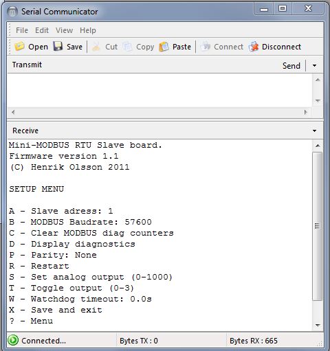
Using the setup-mode.
As soon as the JP1 jumper
on the board is shorted the firmware stops responding to
MODBUS requests, forces a baudrate of 57600-8-N-1 and
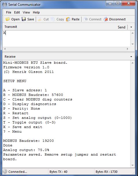
enters setup mode. If you have a terminal emulator (Putty,
Teraterm, Hyperterminal etc) connected you'll get a
short menu, looking something like this:
-
A - Sending A3<ENTER>
changes the slave adress to 3.
-
B - Changing
the baudrate is just as easy but the various
baudrates corresponds to a single digit number like
this: 0=2400, 1=4800, 2=9600, 3=19200, 4=38400,
5=57600, 6=115200 so to change the baudrate to
115000 you type B6<ENTER>
-
C - Sending C<ENTER>
will clear all the MODBUS diagnostic counters.
-
P - Sending P0<ENTER>
gives you NONE as parity, sending P1<ENTER>
gives you EVEN.
-
R - Sending R<ENTER>
will restart the board. If changes have been made
but not saved they will be lost. Remember that if
you've placed a jumper across JP1 the board will
immediately re-enter setup-mode. If that's not your
intention make sure to remove the jumper prior to
restarting the board.
-
S - The analog
output can be controlled in 0.1% resolution by
sending S123<ENTER> for 12.3%, S789<ENTER>
for 78.9%, S1000<ENTER> for 100% and so on.
Sending values above 1000 will set the output to
100%.
-
T - The digital
outputs can be toggled by sending Tn<ENTER>
where n is the number of output (0-3) you wish to
toggle. Example: T2<ENTER>
-
W - If this is
set to anything but 0 the watchdog feature is
enabled. This feature will turn off the outputs if
no MODBUS frame is received within the specifed
time. The time is specified in units of 100ms so
sending W15<ENTER> will set the timeout threshold to
1.5s. The state of the coil registers are left
unaltered and the outputs will be renabled with
states reflecting the coil registers as soon as any
valid MODBUS frame is received. This feature was
added in firmware v1.10
-
X - Will save
your current settings (slave adress, baudrate and
parity) to the non volatile EEPROM memory after
which you need to restart the board by either
sending R<ENTER> or cycling power to the
board in order for the new settings to be used.
-
? - Sending ?<ENTER>
will reprint the menu with the current settings.
Note that the displayed settings may or may not have
beed saved.
-
D - Sending D<ENTER>
gives you the following diagnostics menu:
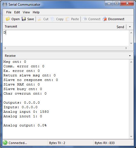
The first 8 lines are the
MODBUS diagnostics counters. The first shows how
many MODBUS messages the device has detected - all in
all. The 4th shows to how many of those messages the
slave have responded. For more details about those and
the other counters please see the MODBUS protocol
specification.
At the bottom half you can
see the state of digital outputs, digital inputs, the
two analog inputs and the analog output. The values does
not "auto-update" on screen so you need to send D<ENTER>
again to "refresh" the screen.
Anytime you send a valid
command you'll get a response. For example:
-
If you send B3 to change the baudrate to 19200 the board will respond
with MODBUS Baudrate 19200
-
If you send T2
to toggle output 2 the board will respond with
Done
-
If you send S750
to set the analog output to 75% the board responds
with Analog Output 75.0%
-
If you send X
to save the settings the board will respond with
Parameters saved. Remove setup jumper and restart
board.
MODBUS Adresses
|
|
MODBUS Adress |
Accesses |
Function code |
Comment |
|
|
|
|
Read |
Write |
|
|
|
Coil 0 |
Output 0 |
1 |
5, 15 |
|
|
|
Coil 1 |
Output 1 |
1 |
5, 15 |
|
|
|
Coil 2 |
Output 2 |
1 |
5, 15 |
|
|
|
Coil 3 |
Output 3 |
1 |
5, 15 |
|
|
|
Coil 4 |
Output 0 (blink) |
1 |
5, 15 |
v1.10 |
|
|
Coil 5 |
Output 1 (blink) |
1 |
5, 15 |
v1.10 |
|
|
Coil 6 |
Output 2 (blink) |
1 |
5, 15 |
v1.10 |
|
|
Coil 7 |
Output 3 (blink) |
1 |
5, 15 |
v1.10 |
|
|
|
|
|
|
|
|
|
Input 0 |
Input 0 |
2 |
N/A |
|
|
|
Input 1 |
Input 1 |
2 |
N/A |
|
|
|
Input 2 |
Input 2 |
2 |
N/A |
|
|
|
Input 3 |
Input 3 |
2 |
N/A |
|
|
|
|
|
|
|
|
|
|
Input reg 0 |
Analog input 0 |
4 |
N/A |
|
|
|
Input reg 1 |
Analog input 1 |
4 |
N/A |
|
|
|
Input reg 2 |
Inputs 0-3 |
4 |
N/A |
|
|
|
Input reg 3 |
Diag counter 0 |
4 |
N/A |
|
|
|
Input reg 4 |
Diag counter 3 |
4 |
N/A |
|
|
|
|
|
|
|
|
|
|
Holding reg 0 |
Analog out 0 |
3 |
6, 16 |
|
|
|
Holding reg 1 |
Analog in 0 gain |
3 |
6, 16 |
|
|
|
Holding reg 2 |
Analog in 1 gain |
3 |
6, 16 |
|
A couple of quick notes
here.
-
The four discrete
inputs can be accessed either as single entities (function
code 2) or they can
be read as a bit-packed 16bit value thru input
register 2 (function code 4). In the later case the lowest significant
bit in the 16bit value corresponds to Input 0. Ie. a value of 9 means that Input 3 and Input 0 are "on".
-
Holding registers 1
and 2 can be used to control the gain of the analog
inputs. By default they both contains the value 256 which
is equal to a gain of 1. If the value 512 (a gain of
2) is written to Holding Register 1 the value
returned in Input Register 0 will range from 0 to 8192
for the 0-5V input range of analog input 0. Likewise
if the value 128 (a gain of 0.5) is written to
Holding Register 2 the value returned in Input
Register 1 will range from 0 to 2048 for the 0-5V
input range of analog input 1. It does not alter the
analog voltage in any way it just scales the value
returned by the ADC.
-
As described earlier the MODBUS
specification contains a
number of diagnostics counters (8 to be precise). I've "mirrored" two of these to
normal Input Registers making them readable even by
MODBUS masters not supporting the proper function
codes for accessing the diagnostics counters. Input Register 3 contains the
content of Diagnostics counter 0 - which is the
total number of MODBUS messages detected on the bus.
Input Register 4 contains the content of Diagnostics
counter 3 which is the number of MODBUS messages
responded to by the slave.
-
Coils 4-7 accesses the
same physical outputs as coils 0-3 but when coils
4-7 are used the output automatically toggles at
~1Hz. Coils 4-7 have precedence over coils 0-3
meaning that whenever coils 4-7 are '1' the output(s)
will blink regardless of the state of coils 0-3.
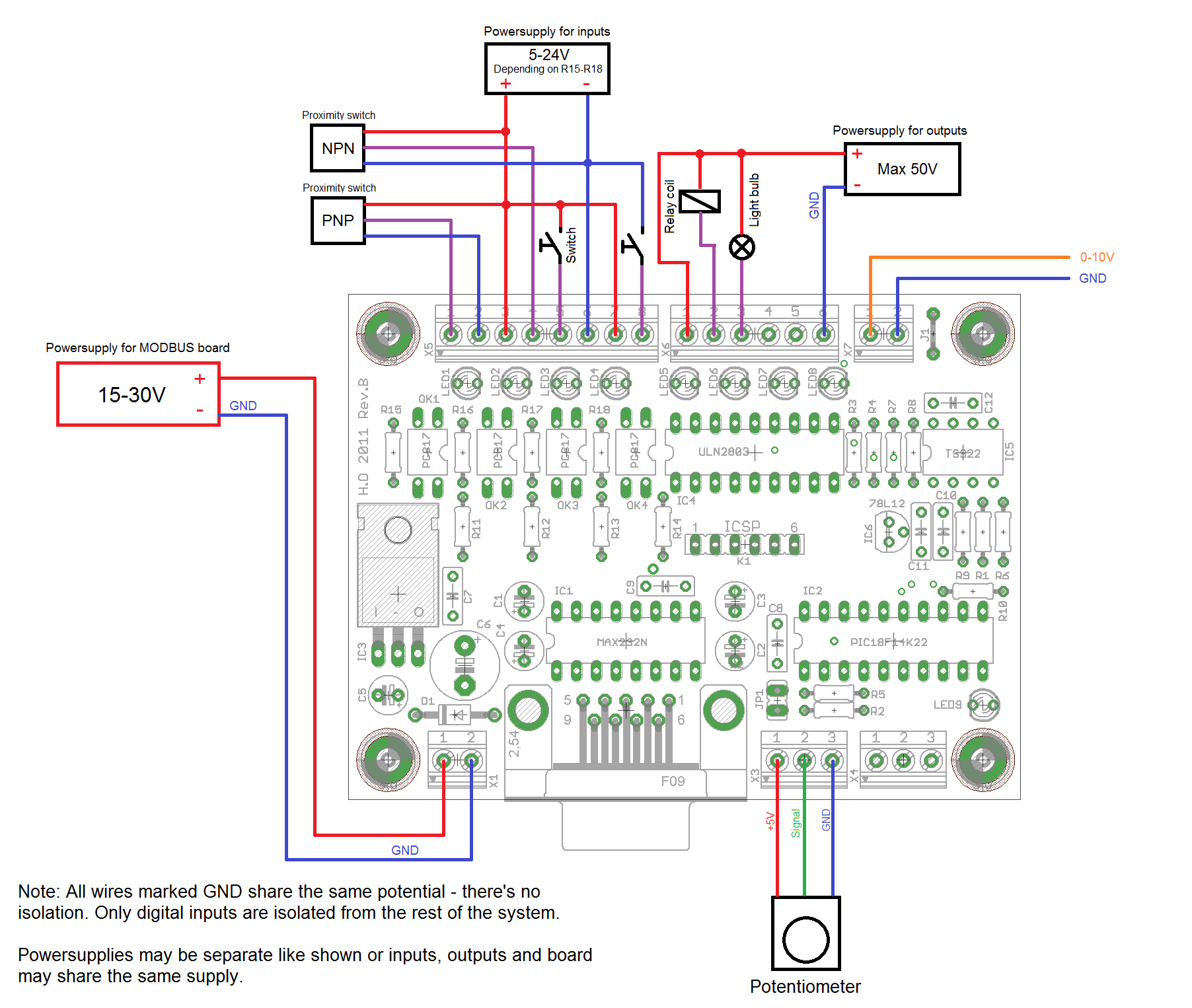
Connecting to the real
world
Here's an example
of the board wired up to a couple of different devices.
I apologize for the crude MS Paint drawing.
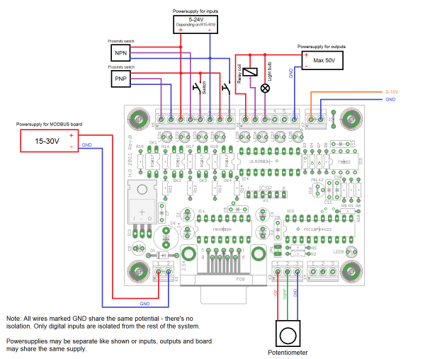
Because the inputs exposes
both legs of the opto-isolator LED they are very
flexible. They can easily be interfaced to both PNP and
NPN type switches and since they are isolated from each
other (and the rest of the board) they don't have to
share the same powersupply or ground even if that is how
it's pictured here. You can have two 5V inputs, one 12V
and one 24V input if that's what you want.
The outputs are open
collector type meaning they "switch to ground". This
means that in theory the supply voltage for the devices
being
switched by the outputs can be different for all four
outputs (12V lightbulb on output 1 and 48V relay on
output 2) but that presents a problem for the internal
clamp diodes in the ULN2803. If you wish to switch loads
with different supply voltages you should add external
protection/clamp diodes and leave terminal (1) on X6 unconnected. Note that the GND connection
for the outputs is not isolated from GND for the board itself.
Finally, you don't have to
use three separate powersupplies like shown above. If
all your devices operates on the same voltage you can
use a single supply.
Downloads
Here you can download the
various files needed for the project. The design file
package contains the EAGLE schematic and board layout
files, the Gerber and Excelon files needed to get the
board fabricated by a board house (I used SeeedStudio),
the BOM for the particular revision of the board and a
.pdf version of the schematic.
The firmware package
contains the .hex file to be programmed into the the PIC
and a .txt file containing release/change notes.
Please note: The source
code for the firmware is not included and I currently
don't have any intention to release it. One of the
reasons for doing this project was to show some of the
capabilities of the MODBUS "driver" I've developed for
the PBP compiler. My intention is to license that driver
to other developers using PBP who are looking for a
MODBUS driver. This application works as a "demo" for
that driver. So, the source code is not available.
I've put together a
small tutorial on how to setup Mach3 to talk to the
MiniMODBUS board.
Kits and bare boards
available
If you're interested in
building a miniMODBUS board but don't want the hassle of
making or ordering PCBs, sourcing components and getting
the firmware flashed into the microcontroller I can now
help with that.
Bare board ($15USD,
shipping included)
You'll get a bare PCB of
the latest revision (currently Rev.C), professionally
manufactured. The cost is $15USD including a flat rate
shipping (additional boards are $10USD). To keep the
cost down the parcel is sent as normal mail so there's
no tracking or insurance. If you feel that you want or
need tracking etc please contact me.
Kits ($65USD, shipping included)
You'll get a PCB of the
latest revision (currently Rev.C) and all components needed, including the microcontroller
programmed with the latest firmware (currently v1.1).
The cost is $65USD which includes flat rate
international shipping
with tracking.
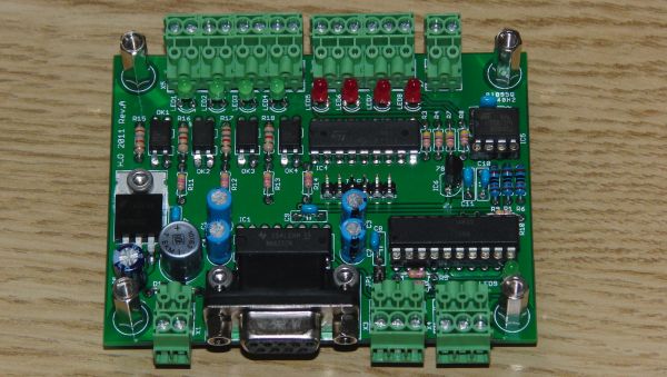
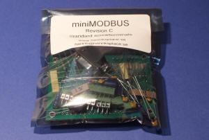
Please note that the kits
are supplied with the standard type 3.5mm pitch
screwterminals, not the pluggable ones shown in the
photos at the top of the page. You can see the ones
supplied with the kit thru the plastic bag in the above
photo.
If you want to sourde the
components yourself but don't have access to a PIC
device programmer I can also supply the PCB with the microcontroller
mounted and programmed with the latest firmware version. The cost
is $25USD including postage (no tracking).
Payment is best handled
thru PayPal, my account is the same the same as the
E-mail adress shown below.
If you build a device, in
any way shape or form, please
drop me a line. Same thing applies if you have a problem
or question or if you're interested in a kit or blank PCB. Adress is:
henrik[at]henriksplace[dot]se
|