|
To be able to make the
robot balance I realised I needed some sort of control
algorithm and I decided that a PID regulator probably
would provide the the largest chance of success.
To
develop and test the code for the PID regulator I used
the same approach as the nBot's creator with a pole
pivoting on top of the robot. A potentiometer
measures the angle of the pole and sends that value the
PIC's onboard A/D converter. The A/D converter sends the
value to the PID regulator whose job is to calculate how
to drive the motors so that the pole remains upright.
A PID regulator is
basicly three regulators running in parallel, each
acting on the Error
signal, in other words the difference between the
desired value and the actual value. Each regulator, or
term, has it's
own gain, that way you can adjust how the regulator
responds to various situations.
-
The P-term
is the proportional term. The larger the error is
the more it will contribute to final output of the
regulator.
-
The I-term
is basicly the sum of all errors in the past. That
is, the longer there's an error present at the input
the more will the I-term contribute to regulators
total output.
-
The D-term
is the derivative or difference between the current
error and last error. This can respond quickly to
sudden changes in the error signal and as well as
having a damping effect on the total output when the
actual value is getting closer to the desired.

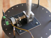
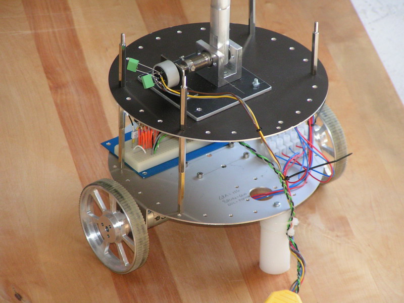
Here's two photos of
the testbed. The first shows the overall mechanical
platform. The motor driver IC's are mounted on a
solderless breadboard on the lower deck and the pivot
joint for the inverted pendulum is mounted on the second
deck.
There's two support
'struts' acting as casters that prevents the robot from
tipping in any direction. For this test setup the signal
from the potentiomter as well as power and PWM signals
to the motor drivers were fed to the CPU via cable so that I didn't
need to worry about battery voltage or my PIC development
board suddenly taking off, heading for the wall.
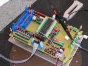
Here's a shot of the
PIC development board. The black cable coming in from
the lower right corner is the power to and signal from the potentiometer
and the grey and green ones are the PWM and direction
signals to the motor drivers. This board will eventually
be replaced with one dedicated to the robot.
After quite a few hours (days
actually) of coding and trial and error I finally
managed to get the robot to balance the pole (well
almost). Here's a couple of low-res videos of the
balancing act.
After I got the robot to
balance the pole I was eager to make it balance itself.
<BACK>
<NEXT>
|