|
Robots
- Two wheeler - Balancing.
|
To be able to balance
on two wheels the robot needs to know how much it is
tilted from the vertical plane. This is usually
achieved by using two different sensors, one
accelerometer and one rate gyro.
The accelerometer
measures static and dynamic acceleration where static
acceleration can be converted to tilt. I decided to
go with the ADXL203 by Analog Devices, it has a
measuring range of ±1.7g and outputs a voltage of
±1000mV / g centered around 2.5V - perfect for the PIC's A/D converter.
The rate gyro
measures the rate of turn, I bought the ADXRS150 also
that made by Analog Devices. This sensor outputs a
voltage proportional to the rate of turn,
±12.5mV/°/s in this case. It has a bias of 2.5V (nominally)
so if you were to spin the sensor at 5rpm the output
would be 2.5V ±375mV depending on the direction of
turn.
So, if the ADXL203 can
measure tilt why can't we just use it and be
done with it? Well, the signal from the
accelerometer is proportional to the tilt only
as long as the force of gravity
is the only force acting on the sensor. But in order for the robot to
move it will have to accelerate and this
acceleration will be picked up by the sensor and
trick the PID regulator to believe the tilt angle of the
platform is different from what it really is.
I searched the net
trying to find out exactly HOW the signals from
these two sensors should be combined and terms like
complementary filters
and Kalman filtering
kept turning up. Some quick research on the subjects
indicated that the math involved was way over my head.
So now what....
 Well,
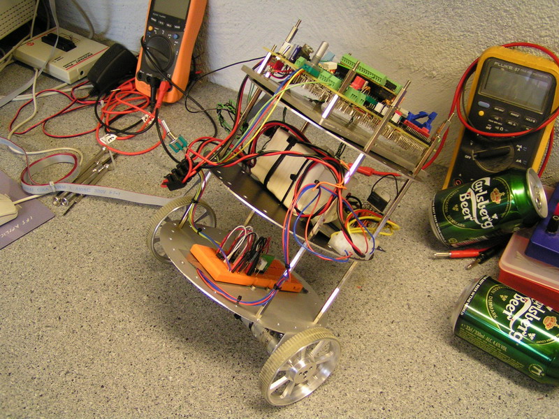
what's better than a little trial and error? I
mounted the two sensors on a solder less breadboard,
added another deck to robot and mounted the PIC
development board to it and started testing. Hope
you don't mind the beer cans in the photo, they
where used as a stand for the robot....well, that
too.....
After a while I had a
robot that at least seemed like it wanted to stay
upright. Basically, what I ended up with was to just
sum the signals from the accelerometer and gyro and
feed that to the PID regulator.
Here's a couple of
low-res videos of the robot trying to stay balanced. Well,
what's better than a little trial and error? I
mounted the two sensors on a solder less breadboard,
added another deck to robot and mounted the PIC
development board to it and started testing. Hope
you don't mind the beer cans in the photo, they
where used as a stand for the robot....well, that
too.....
After a while I had a
robot that at least seemed like it wanted to stay
upright. Basically, what I ended up with was to just
sum the signals from the accelerometer and gyro and
feed that to the PID regulator.
Here's a couple of
low-res videos of the robot trying to stay balanced.
This gave me enough
confidence to continue the development. As can be
seen in the videos the robot tends to run back and
forth quite a bit. This is because the robot has no
information of the actual position. To solve this I
wanted to put encoders on the wheels so that the CPU
can measure the actual distance traveled and adjust
the set point for the desired tilt as a mean to drive
the robot back to it's starting position, or any
position.
Another advantage
of the encoders on the wheels is that the CPU may be
able to measure the actual acceleration of the
platform and adjust the value from the accelerometer
accordingly, effectively removing the platforms
acceleration from the reading. Well, that's the
theory anyway....
One more thing that
that the videos shows is that it tends to vibrate
and oscillate quite a bit when it's being pushed.
That's actaully what I'm trying to induce in the
first video above. I believe this is partly due to
the accelerometer picking up the robots
accelleration and partly because the gyro is quite
sensitive and the D-term of the regulator acts hard
on any "noise" in the input signal.
But...to be able to
fit the encoder I had to rebuild the base of the
robot.
<BACK>
<NEXT>
|
|