|
The drawbar assembly
consists of these three main parts:
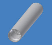
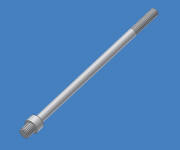
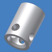
Starting from the left we
have what I call the "tube" then there's the actuall
drawbar and to the right we have the gripper. The
gripper fits inside the lower part of the tube so that
when the drawbar pulls it up into the tube the chamfer
in the tube forces the balls to grip around the
toolholders pullstud. The tube is made from SS2511 steel
and the lower half, where the gripper sits is hardened.
The gripper is also made from SS2511 and hardened.
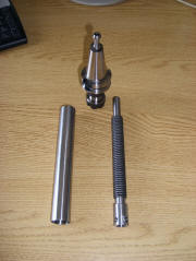
This photo shows the
finished parts for the drawbar assembly before sending
them out for hardening. There's also a BT30-ER16
toolholder with pullstud.
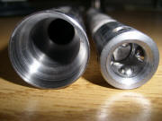
Here's a shot of the tube
and the gripper with the balls mounted. They are 6mm
steel "ball bearing balls" and the holes in the gripper
are machined so that they can't fall out on the "inside"
of the gripper.
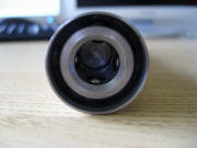
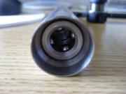
These two last photos
shows the gripper "in action". To the left the drawbar
is pushed down and the balls are free to be pushed out
of the gripper so that the toolholder can be released.
To the right the drawbar
is pulled up and the balls is pushed in by the chamfer
it the tube.
<BACK> <NEXT>
|

