|
When the BT30 spindle
project kind of failed I kept using the ER16 collet
spindle for a while but in November 2013 I decided to
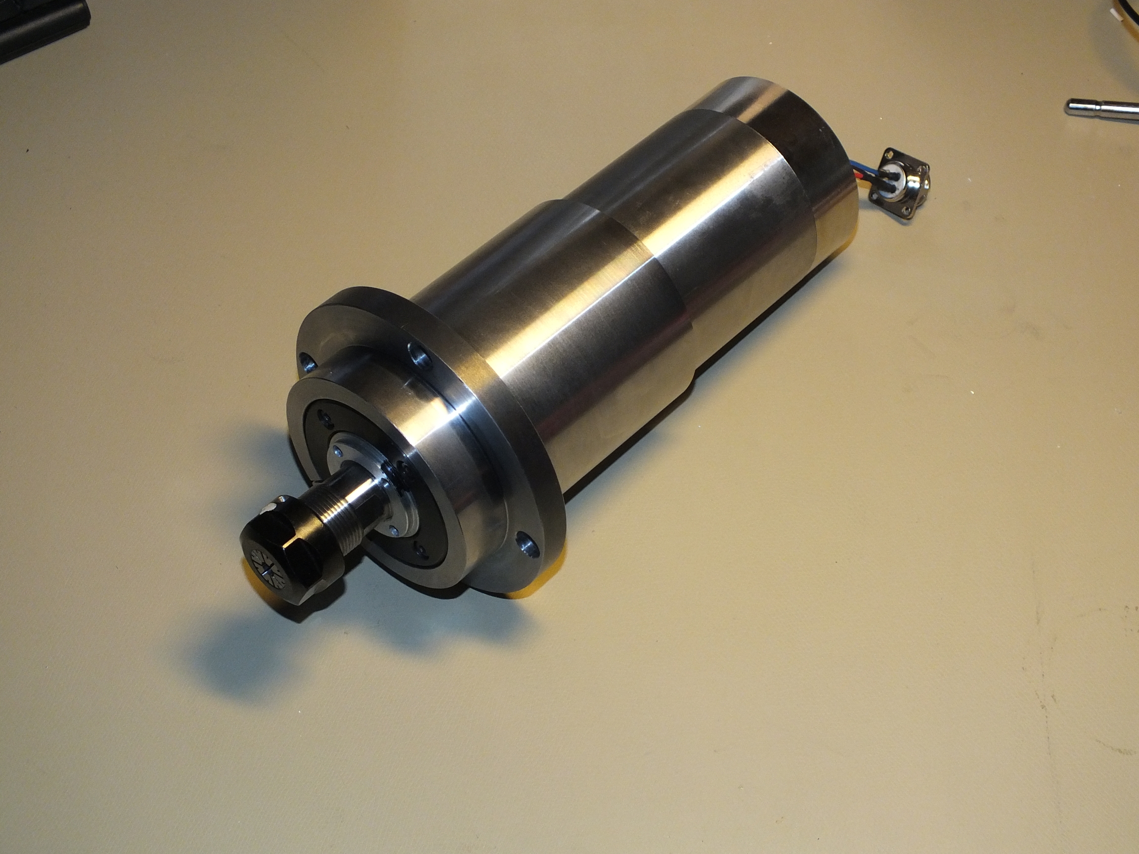
upgrade the machine to one of the popular Chinese 2.2kW
24krpm water cooled spindles. I found one on EBAY which
had a fairly short nose on it which I liked so I picked
that one up for $300 including shipping.
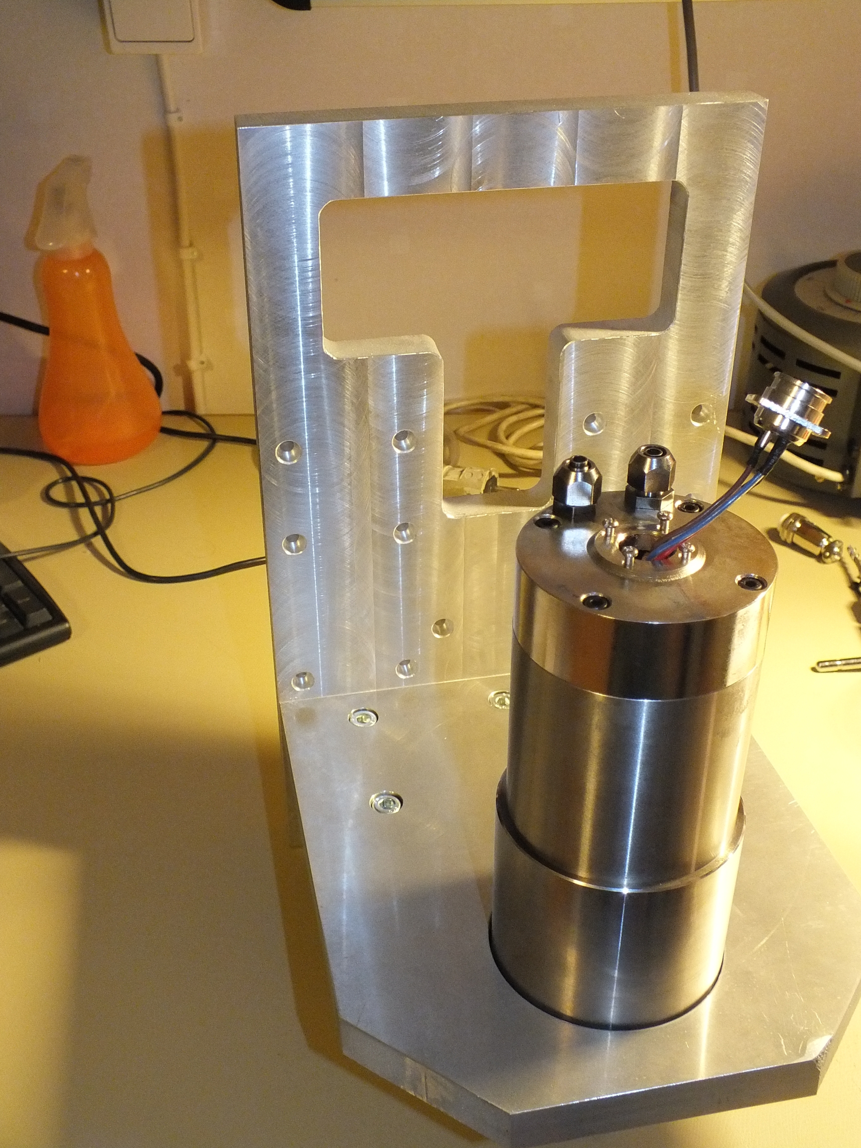
I had some aluminium
plates intended for mounting the BT30 spindle to the
machine which I decided to use for this spindle instead.
In order to do that I needed a way to mount the spindle
like I intended to mount the BT30 spindle, ie via a
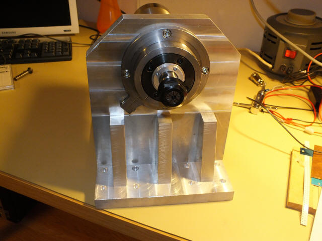
flange. So I built a sleeve/flange/clamp type of
adapter:
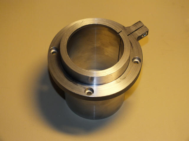
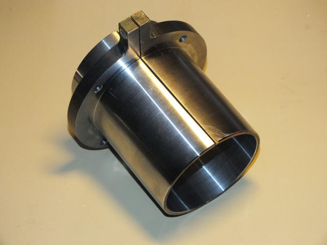
The internal bore is a
nice tight fit to the 80mm outer diameter of the spindle
and tightening the clamp screw seams to lock it place
firmly, seams to do the job.

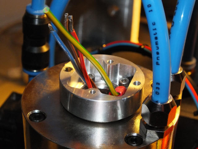
You can see the dicky
connector hanging out at the back. Although the quality
was a bit better than I thought it would be this was one
thing I decided I had to change before even powering the
thing up. There's not even a proper earth connection in
that thing but more on that later on.
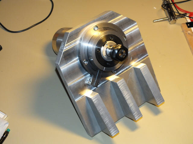
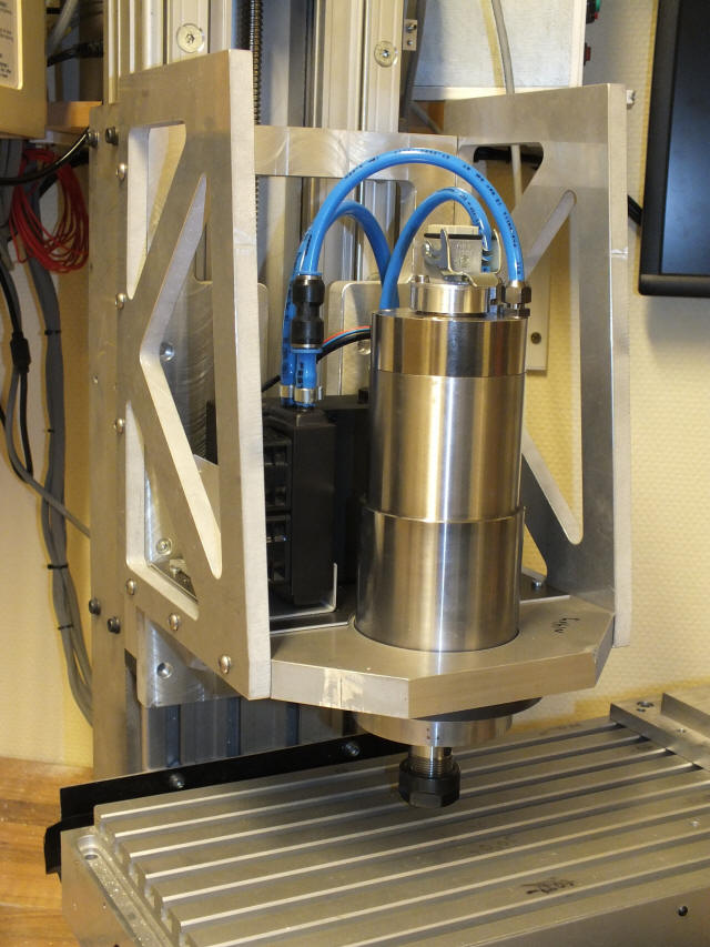
The spindle with its
flange adapter is then mounted to the bottom plate of
the new Z-axis assembly:
And then the bottom plate
is mounted to the back plate:

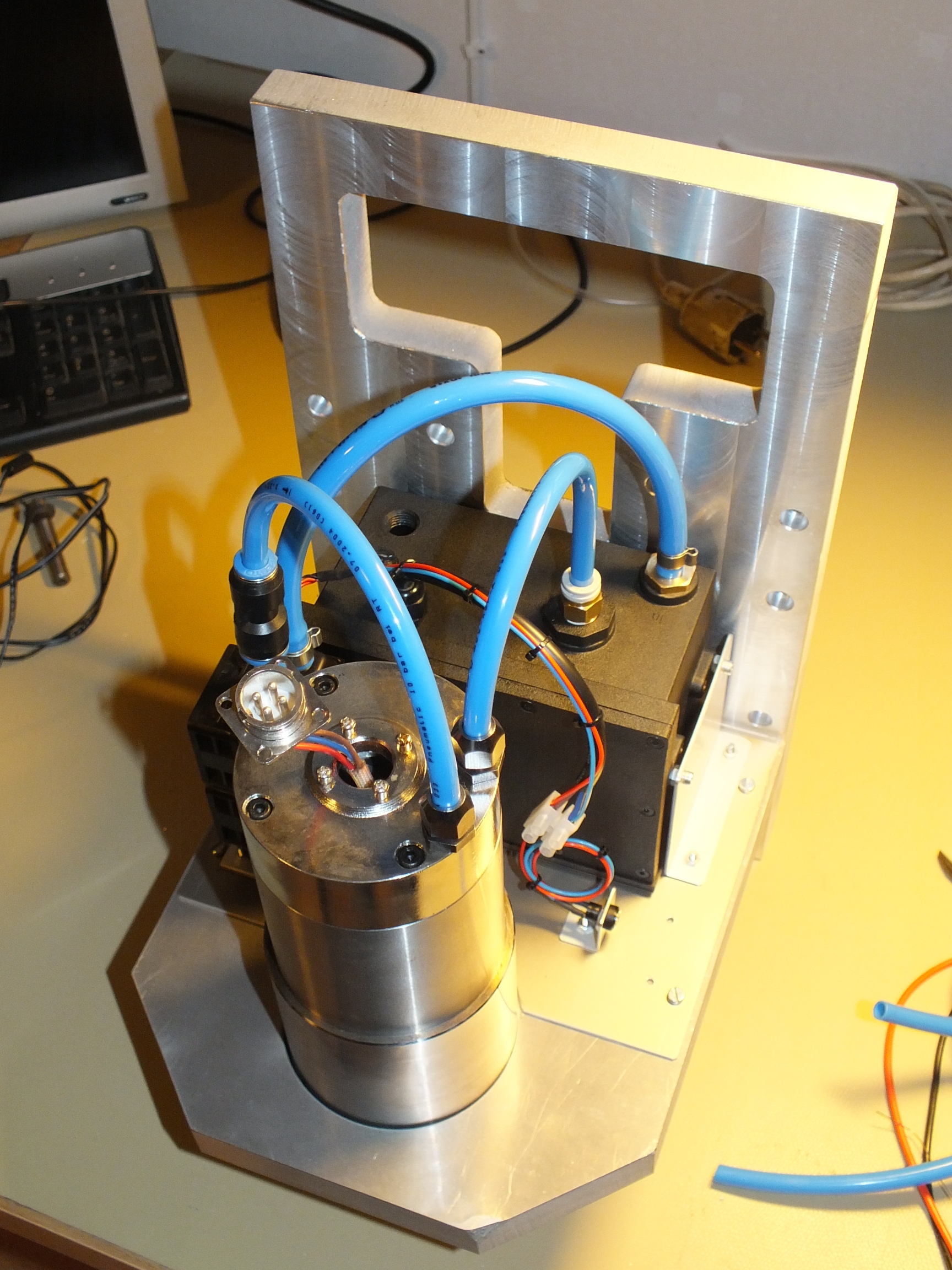
Instead of having to run
water lines back and forth with the risk of them wearing
out and eventually rupture and leaking I decided to at
least try fitting the cooling system to the Z-axis
assembly. To be honest, I didn't do much research into
how much cooling these things really need so I may end
up redoing the whole lot but anyway, here's what I came
up with:
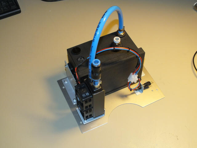
This is a PC watercooling
reservoir/pump, model XSPC 750 v4 to be precise
and a small radiator, model MagiCool Mini II with
2 40mm fans mounted to it. The pump is specified to 12.5
litres per minute which feels like more than enough (provided
it can push it thru the channels of spindle that is).
The issue I'll most likely have, if any, is that the
radiotor/fan assembly is too small and won't be able to
dissipate the heat. There's room for one more
radiator/fan assembly of the same size so if it turns
out to alomst work I might fit that. Otherwise I'll have
to revert to something bigger and have the system off
the Z-axis assembly.
Anyway, the cooling system
sub assembly sits right behind the spindle motor, like
this:

Right, back to the
connector.
This is a motor designed
to run at 220V 3-phase. However, I'd like to run it
using the inverter I already have and that's designed to
be powered from 400V 3-phase which means that the
DC-link in the inverter is aroung 560V and this is the
voltage that the wiring and connectors needs to be able
to handle, with margin to spare. There's no markings
what so ever on the connector on the spindle and I
didn't feel comfortable using it - especially so when
there's not even a proper earth connection included.
So I decided to use a
4-way HARTING connector specified for the job. In order
to fit that I had to fabricate a little adapter. (This
aproach by the way was inspired by another CNC machine
builder so I can't take all the credit):
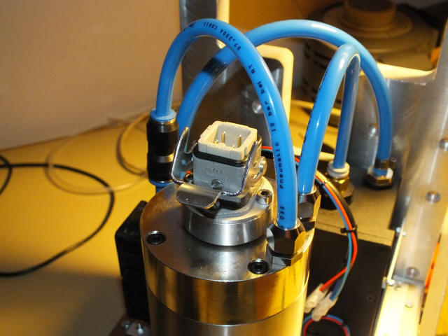
Now, that's more like it
if you ask me.
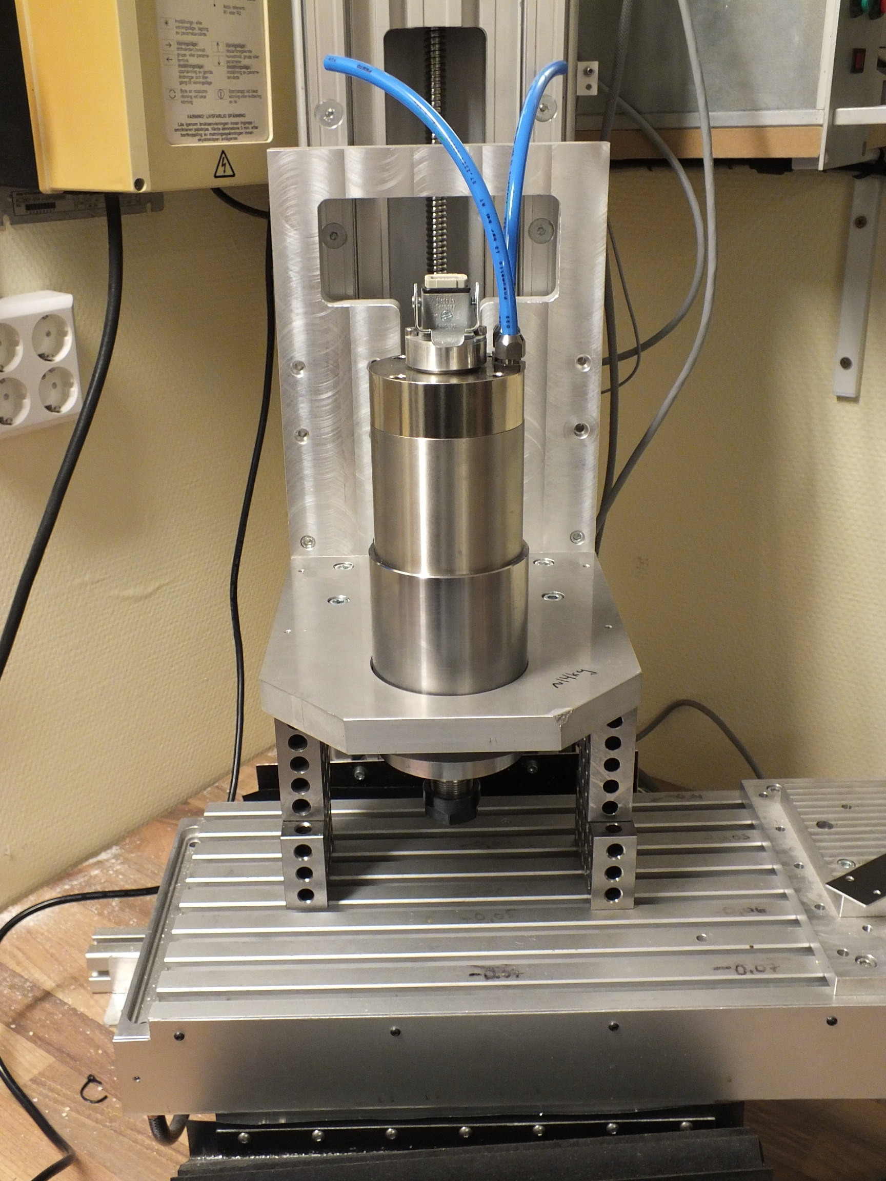
Then it was time remove
the old Z-axis assembly from the machine and mount the
new one. Not much to say about it really but here are a
couple of photos:


My intention was to use
the same inverter I had been using for the ER16 spindle.
This was a 3kW inverter and this new spindle is a 2.2kW
motor BUT the inverter was rated for 3kW at 400V output
while the new spindle is 2.2kW at 220V so the actual
output current of the 3kW inverter wasn't quite up to
the task. Never the less I thought it could work since I
most likely won't run at full power for very long
periods and it did work - initially.
As I was setting up the
inverter I played around with the setting for the
switching frequency (or carrier frequency as it's
sometimes called) and all of a sudden the inverter
tripped with an over current fault. After some tests it
turned out that it kept tripping as soon as the output
was turned on, no matter if there was anything connected
to it or not.
Looking at the manual for
the inverter I noticed a little tiny note right next to
the setting for the inverter frequency saying that one
should contact the factory for derating figures when
raising the swithcing frequency - oops. I suspect me
increasing the switching frequency might be what killed
the inverter, I don't know. Anyway, it was 1992 vintage
and underpowered to begin with so it had to replaced
with something.
I ended up getting a used
4kW Danfoss VLT MicroDrive for a good price. It's
specified to 9A continous output and the motor at
8.something so it should be a good match. I've done the
initial setup of it and it seams to work just fine.
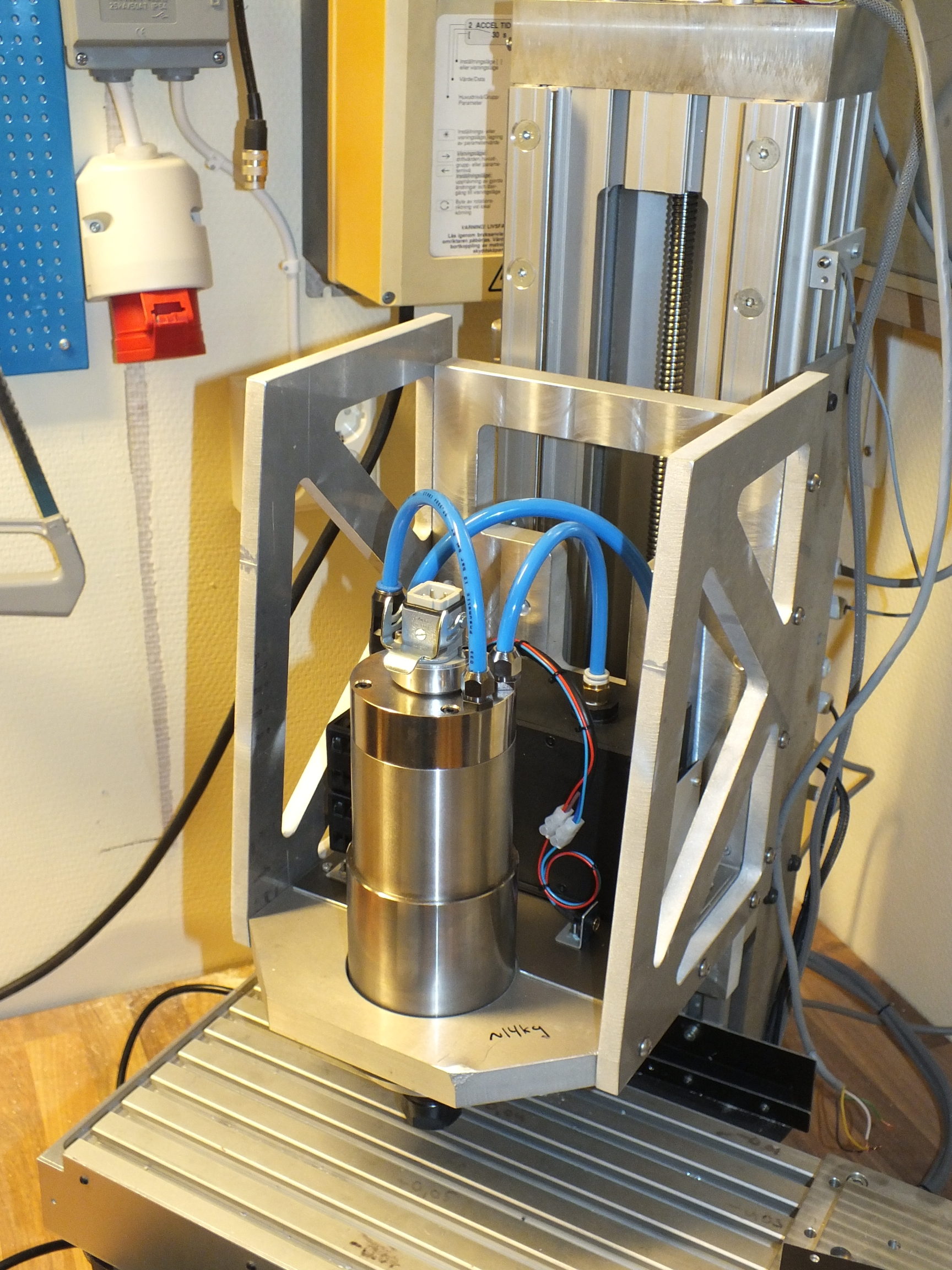
Here's photo of the new, almost finished, setup:

As of this writing I
haven't yet connected the inverter to contol box so that
it can be controlled from Mach3. This inverter has a
MODBUS interface so I'm thinking of going that route
instead of discrete signals. Doing it over MODBUS allows
some cool feedback from the inverter to be displayed in
Mach3, like motor current, motor power, any warnings and
so on. I'll play with that next.
2013-12-26.
<BACK> <NEXT>
|