|
With the base and wheel supports rebuilt it was time
to tackle the task of reading those encoders. I decided
early on that having a single processor reading both
encoders, reading the gyro/accelereometer, performing
the PID calculations and driving the motors as well as
acting on input from various sensors would be to
much to handle, not for the PIC, but for my programming
skills.... I instead opted for a dedicated PIC for each
wheel. I decided to go for the
PIC18F2431 because it is designed for motorcontrol
applications like this and it has a hardware interface
for a quadrature encoder so the software running in the
PIC doesn't have to do the actuall counting of the
encoder pulses, it's all taken care of in hardware and
the software just needs to read the counters register.
Since the robot has two wheels and thus two motors there
needs to be two motor controllers. I opted to make them
communicate with the main CPU thru a RS485 network. The
main CPU is the 'master' and the two controllers are the
slaves. The main CPU sends commands containg an adress
that the slaves evalutes and if the adress matches that
of the particular slave the data is meant for it and
will act uppon it. For example change the speed, report
current position, change PID parameters etc.
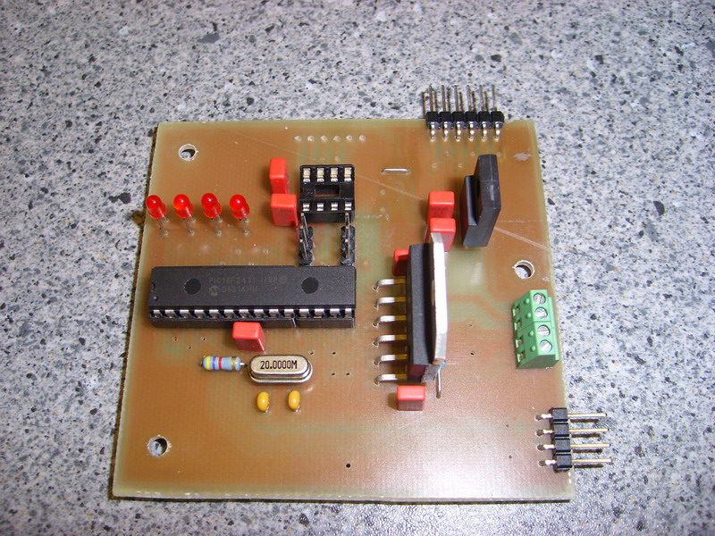
Here's a
screenshot of the schematic as it stands today, a photo
of one of the bare PCB's and one of the populated
protoypes.
(2007-02-25)
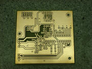

The powersupply and the motor connects to the
screwterminal on the right hand side of the board. Below
that there's a 4-pin header for the encoder. In the
upper right hand corner is a 5-pin header for
reprogramming and debugging and next to it is the
connections for the RS485 bus, external +5V and GND and
two spare connections. The programming header doesn't
have any traces going to the PIC on this board revision.
I solderd wires on the bottom side of the board for
that.....bit of a mess, I know, but for a prototype it
works. The LED's are simply for status signaling. and
debugging purposes.
The control-loop inside the PIC is
interrupt driven and runs at 1220Hz. Each
interrupt the position is read and compared to
the commanded position. The error is calculated and run
thru a PID filter. The output from the PID filter then
sets the direction bit and tells PICs PWM module what to
output to the
LMD18200.
<BACK>
<NEXT>
|